 yk-fujii
commented
1 year ago
yk-fujii
commented
1 year ago Hi QQting,
Thanks very much for the great PR. We will start reviewing and testing.
Closed QQting closed 10 months ago
yk-fujii
commented
1 year ago Hi QQting,
Thanks very much for the great PR. We will start reviewing and testing.
yk-fujii
commented
1 year ago Hi @QQting
RQX59G jetpack 5.0 + Leopard GMSL board (MIPI 2-lane) RQX59G jetpack 5.0 + ADLINK GMSL board (MIPI 4-lane)
How do you identify between the above two?
I think we need to switch num_lanes , bus-width between 2 and 4 in the device-tree, is this unnecessary?
 QQting
commented
1 year ago
QQting
commented
1 year ago Hi @yk-fujii
I've modified make_overlay_dts_roscube-orin.py to deal with num_lanes, bus-width, and serdes_pix_clk.
I use gpiod to get the 4 GPIO values to distinguish the GMSL Board ID, please see the python scripts below: https://github.com/Adlink-ROS/tier4_automotive_hdr_camera/blob/c5d4ad2e18ce833de81fbb23ca702e653aac9ff3/drivers/src/make_overlay_dts_roscube-orin.py#L13-L43
I also added the gpiod into debian/control as a dependent package.
https://github.com/Adlink-ROS/tier4_automotive_hdr_camera/blob/c5d4ad2e18ce833de81fbb23ca702e653aac9ff3/drivers/debian/control#L12
yk-fujii
commented
1 year ago @QQting Thanks, I understand.
Could you please add comments referring to the review above? Other code looks good.
We have the RQX-59G + Leopard Imaging version, so I will test it and then merge.
QQting
commented
1 year ago We have the RQX-59G + Leopard Imaging version, so I will test it and then merge.
Can I know which FPGA version you are using now?
(get version value by command i2cget -f -y 2 0x66 0x01)
Because what I've tested is based on version 0x24
By the way, The frame sync docs are published here: https://adlink-ros.github.io/roscube-doc/roscube-x/gmsl_camera/frame_sync.html#tier-iv-c1-c2-frame-sync
yk-fujii
commented
1 year ago Sorry for late...
Can I know which FPGA version you are using now?
We have encountered 0x21, 0x23, 0x24 for FW versions, and it is not always 0x24.
I don't have the resources to check the operation, so I asked another member to do it. It is assumed that it can be confirmed and merged in about a week.
 bookbridge
commented
11 months ago
bookbridge
commented
11 months ago Hi @QQting, Sorry for keeping you waiting.
We are preparing our code to merge your changes, as we have several updates from the point you forked the code. We will provide the patch file so you can apply it to your own code, including your modification/contribution, without causing conflict. Please wait a little bit more.
By the way, we have one question regarding the control of MAX9296. It seems that currently, you don't control MAX9296's HW reset (PWDN) pin. Do you have any specific reason? We think it would be useful because if we can control this, we can also reset the camera side without rebooting the whole system.
QQting
commented
11 months ago By the way, we have one question regarding the control of MAX9296. It seems that currently, you don't control MAX9296's HW reset (PWDN) pin. Do you have any specific reason? We think it would be useful because if we can control this, we can also reset the camera side without rebooting the whole system.
Hi @bookbridge
I don't know the reason for the original design. But I know the PWDN pins of MAX9296 are connected to FPGA. And we can also write the register to control the PWDN pins.
For example:
# enable 4 PWDN pins for dser0/1/2/3
sudo i2cset -f -y 2 0x66 0x04 0xF0
# enable PWDN pin for dser0 only
sudo i2cset -f -y 2 0x66 0x04 0x10
# enable PWDN pin for dser1 only
sudo i2cset -f -y 2 0x66 0x04 0x20
# enable PWDN pin for dser2 only
sudo i2cset -f -y 2 0x66 0x04 0x40
# enable PWDN pin for dser3 only
sudo i2cset -f -y 2 0x66 0x04 0x80
Below table is the register address 4 of FPGA
Furthermore, we are able to control the MAX20089 chip to power on/off the MAX9295 and Camera sensor by following commands:
# disable power for fakra connector port1 and port2
sudo i2ctransfer -f -y 30 w2@0x28 0x01 0x00
# disable power for fakra connector port3 and port4
sudo i2ctransfer -f -y 31 w2@0x28 0x01 0x00
# disable power for fakra connector port5 and port6
sudo i2ctransfer -f -y 32 w2@0x29 0x01 0x00
# disable power for fakra connector port7 and port8
sudo i2ctransfer -f -y 33 w2@0x29 0x01 0x00

# enable power for fakra connector port1 and port2
sudo i2ctransfer -f -y 30 w2@0x28 0x01 0x0F
# enable power for fakra connector port3 and port4
sudo i2ctransfer -f -y 31 w2@0x28 0x01 0x0F
# enable power for fakra connector port5 and port6
sudo i2ctransfer -f -y 32 w2@0x29 0x01 0x0F
# enable power for fakra connector port7 and port8
sudo i2ctransfer -f -y 33 w2@0x29 0x01 0x0F
Maybe you can help to integrate these I2C commands into the driver codes.
QQting
commented
11 months ago Hi @QQting, Sorry for keeping you waiting.
We are preparing our code to merge your changes, as we have several updates from the point you forked the code. We will provide the patch file so you can apply it to your own code, including your modification/contribution, without causing conflict. Please wait a little bit more.
I can help to merge the latest codes from tier4:main branch due to there are some modifications for applying to L4T R35.4.1 in RQX590
bookbridge
commented
11 months ago Hi @QQting, Thank you for your answer! We'd like to plan the integration of PWDN control as a driver. Again, Please wait a little bit more until we provide a patch to merge your code. Thank you four your patience.
QQting
commented
11 months ago @bookbridge
Do you know why the default values are 0xCAFE? https://github.com/tier4/tier4_automotive_hdr_camera/blob/0902c0d29bb5ec43991eed4a04a3b6d03f951716/drivers/src/tier4-isx021.c#L357-L359
Could I change these value to <0, 1, 1> according to tier4-isx021.conf? https://github.com/tier4/tier4_automotive_hdr_camera/blob/0902c0d29bb5ec43991eed4a04a3b6d03f951716/drivers/debian/etc/modprobe.d/tier4-isx021.conf#L12
bookbridge
commented
11 months ago @bookbridge
Do you know why the default values are 0xCAFE?
@QQting It is set intentionally not meaningful number, as we'd like to detect if the config file (tier4-*.conf) takes effect or not.
bookbridge
commented
11 months ago @QQting, we are reviewing https://github.com/tier4/tier4_automotive_hdr_camera/pull/12/commits/dc390a9425a17c9c3aabfaac439ad2cc50679537.
In this commit, it seems that you changed the slave address of isx021 from 1b, 1c to 5b, 5c. Do you have any reason for this? For all the other ECUs, we are using the same 1b and 1c and we would like to keep it, if possible.
Could you please elaborate on the reason for this modification?
QQting
commented
11 months ago <0x1c> at i2c@c250000 is in use, which is ALC5420 audio codec in RQX590. If we use <0x1c> for camera, then the Built-in Audio will not work. What's your suggestion for the i2c address conflict? - Keep <0x1c> for camera and not use built-in audio? - Or change camera to another i2c addess?@QQting, we are reviewing dc390a9.
In this commit, it seems that you changed the slave address of isx021 from 1b, 1c to 5b, 5c. Do you have any reason for this? For all the other ECUs, we are using the same 1b and 1c and we would like to keep it, if possible.
dc390a9#diff-5e1400b5f5956427e8efaffcd8f11a2c6deb13bd325c2416d3eeafcfbd56e3d2R1204
Could you please elaborate on the reason for this modification?
bookbridge
commented
11 months ago Hi @QQting,
Thank you very much for your answer.
The above is my understanding of the i2c structure of the camera system. You still could access the audio codec as its bus number must be different from 0x30 ~ 0x33. Am I saying something that does not make sense?
bookbridge
commented
11 months ago @QQting
Now I understand that the i2c bus address has changed from RQX-58G. Could you provide more detailed information regarding the I2C bus connection, like the picture above? Also, could you please share the H/W information (i.e. datasheet) if there is a change from RQX-58G? At this moment, we are not sure if DTS is correct.
Thank you for your cooperation.
QQting
commented
11 months ago @QQting
Now I understand that the i2c bus address has changed from RQX-58G. Could you provide more detailed information regarding the I2C bus connection, like the picture above? Also, could you please share the H/W information (i.e. datasheet) if there is a change from RQX-58G? At this moment, we are not sure if DTS is correct.
Hi @bookbridge
RQX-58G H/W has no change. The I2C address conflicts only happens on RQX-590 with ADLINK GMSL board.
So, if the i2c address changes only apply to RQX590, is it acceptable for you?
By the way, you don't need to worry about if DTS is correct because I've already tested on both RQX-58G and RQX-590 with 8 pcs C1 cameras. But I don't have C2 cameras on my hand to test.
QQting
commented
11 months ago
The above is my understanding of the i2c structure of the camera system. You still could access the audio codec as its bus number must be different from 0x30 ~ 0x33. Am I saying something that does not make sense?
Yes, you're correct. Actually, the i2c-30/31/32/33 are expanded from i2c_mux, which is at i2c-7 <0x70>. I don't know why the audio codec at i2c-7 <0x1c> will be seen at i2c-30/31/32/33.
More information are listed below:
QQting
commented
11 months ago One thing you have to know, there is an issue about min_gain_value on L4T R35.4.1
Before R35.4.1, the default value is "0". But in R35.4.1, "0" is not allowed, so I've written an exception code in make_overlay_dts_roscube-orin.py. Maybe you can also apply the fix into other python scripts.
bookbridge
commented
11 months ago @QQting Thank you for your comment.
The I2C address conflicts only happens on RQX-590 with ADLINK GMSL board.
RQX-58G -> Xavier RQX-590 -> Orin So, if the i2c address changes only apply to RQX590, is it acceptable for you?
Just to confirm, are we talking about RQX-59G instead of RQX-590 ?? 590 must not have GMSL port.
QQting
commented
11 months ago Just to confirm, are we talking about RQX-59G instead of RQX-590 ?? 590 must not have GMSL port.
Yes, we are talking about RQX-59G. Due to RQX-590 BSP can support not only GMSL board but also FPDL board, so the /proc/device-tree/model is displayed RQX-590.
bookbridge
commented
11 months ago @QQting
Thank you again for your support. Would it be possible for you to provide the original RQX-59G DTS or DTB file that is overlayed? We need to have it in the case of debugging. It seems the one we can access https://www.adlinktech.com/Products/DownloadSoftware.aspx?lang=en&pdNo=2027&MainCategory=ROS2-Solution.aspx&kind=BS is not a release version. I've heard from your colleague that the production version of RQX-59G will include Jetpack5.1.2 (L4T 35.4.1).
QQting
commented
11 months ago Thank you again for your support. Would it be possible for you to provide the original RQX-59G DTS or DTB file that is overlayed?
What do you mean about "the original RQX-59G DTS or DTB file that is overlayed"?
bookbridge
commented
11 months ago @QQting, I meant "the DTS files of RQX-59G without merging camera DTBO"
QQting
commented
11 months ago @QQting, I meant "the DTS files of RQX-59G without merging camera DTBO"
Sure, can I have your email address? I will attach the DTS files and mail to you.
QQting
commented
11 months ago <0x1c> at i2c@c250000 is in use, which is ALC5420 audio codec in RQX590. If we use <0x1c> for camera, then the Built-in Audio will not work. What's your suggestion for the i2c address conflict? * Keep <0x1c> for camera and not use built-in audio? * Or change camera to another i2c addess?
Hi @bookbridge
What's your thoughts about i2c address conflicts?
bookbridge
commented
11 months ago Hi @QQting,
We've discussed this internally and agreed to change the slave address of the cameras. Shall we change the camera address to (1d, 1e)? The reason is that we would like to keep the camera address at the early part of the slave address, as the other device driver implements. The later part (like 5b, 5c as you suggested) might conflict with ISP-related devices.
QQting
commented
11 months ago We've discussed this internally and agreed to change the slave address of the cameras. Shall we change the camera address to (1d, 1e)? The reason is that we would like to keep the camera address at the early part of the slave address, as the other device driver implements. The later part (like 5b, 5c as you suggested) might conflict with ISP-related devices.
Sure, <0x1d> and <0x1e> looks good. I will modify our codes and commit again, thanks.
bookbridge
commented
10 months ago Dear @QQting,
Thanks to your code, we've verified most of the C1/C2 operations with RQX-59G. We've verified the operation in master mode as well as FSYNC auto trigger mode. The remaining point is FSYNC generation from Orin SoC. ("fsync_mode=2" enable FPGA Fsync Manual Trigger mode)
What we tried:
The result is green display, which means FSYNC is not inputted to the camera so the camera does not output the MIPI packet.
Do you have any advice? Or do you have any spec document (or similar) for FPGA?
QQting
commented
10 months ago Hi @bookbridge
The register address and value of FPGA are correct.
Can I know what test environment you are using for test? C1 or C2 camera?
I've used below configuration, and the manual trigger is fine.
/sys/module/tier4_isx021/parameters/trigger_mode (=1)/sys/module/tier4_fpga/parameters/fsync_mode (=2)gst-launch-1.0 -e v4l2src device=/dev/video0 ! 'video/x-raw,format=UYVY,width=1920,height=1280' ! videoconvert ! fpsdisplaysink video-sink=xvimagesink sync=falsebookbridge
commented
10 months ago Can I know what test environment you are using for test? C1 or C2 camera?
For both C1 and C2. Let us try for more.
QQting
commented
10 months ago The result is green display, which means FSYNC is not inputted to the camera so the camera does not output the MIPI packet.
Sometimes the green display doesn't mean the camera not output MIPI data, it may due to skew calibration when MIPI lane speed >= 1.5 Gbps.
Please try sudo ./deskew_max9296.sh before starting stream.
deskew_max9296.zip
bookbridge
commented
10 months ago @QQting Thank you very much for your support & contribution! We've confirmed FSYNC manual generation mode as well. (The root cause was a different FPGA configuration. We've checked your GitHub on how to write FPGA, and with the new FPGA all functions are verified).
QQting
commented
10 months ago Hi @bookbridge
Could you help me to understand what's the application or scenario to use "Manual Trigger Mode"? Why not using "Auto Trigger Mode" for more accuracy?
Furthermore, what do you think about current FPGA design? If we are going to add more features to FPGA, what do you expect for the next version?
QQting
commented
10 months ago Hi @bookbridge
Does C2 cameras (IMX490) only support 10/20/30 FPS slave mode? Could it be triggered by using any other frequency?
bookbridge
commented
10 months ago @QQting
Could you help me to understand what's the application or scenario to use "Manual Trigger Mode"? Why not using "Auto Trigger Mode" for more accuracy?
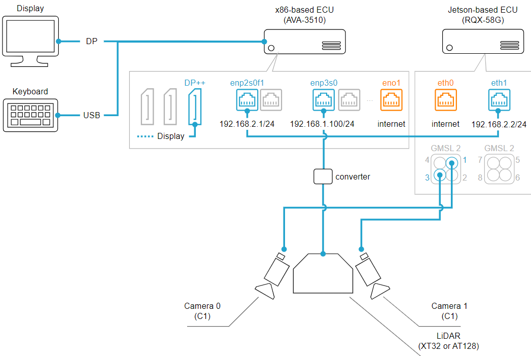
One of the main use-case of triggering is synchronizing the Lidar and cameras. With the current architecture, as described here, Lidar is connected to x86 based ECU and x86-based ECU and ARM ECU (e.g., ROSCube) is time-synchronized by PTP protocol. Because of this architecture, it is required to synchronize the FSYNC triggering timing based on the system (Linux) clock. However, based on the current implementation of FPGA, it is impossible (please kindly correct me if my understanding is incorrect).
This leads us to your second question. it would be nice if we can synchronize the FPGA pulsing timing based on Linux time.
bookbridge
commented
10 months ago @QQting
Does C2 cameras (IMX490) only support 10/20/30 FPS slave mode? Could it be triggered by using any other frequency?
Please refer to HERE. Thanks!

Hi guys!
I'm software engineer from ADLINK, and I've updated many codes based on ROScube-X. Please help to review and merge, thank you!
This driver codes have been tested on the environment below:
i2cget -f -y 2 0x66 0x01)For the fsync feature on ROScube-X, I will update the documents into https://adlink-ros.github.io/roscube-doc/roscube-x/gmsl_camera/index.html later.
Because I don't have any C2 cameras, the driver codes related to IMX390 haven't be tested. Hope you can help verify with C2 cameras.