Closed khalm-github closed 3 years ago
In setup(), you need to define a callback and interrupts:
FD.onReceive(canSniff); FD.enableMBInterrupts();
Then in loop() you need to enable the data buffer: FD.events();
Then make sure your callback exists:
void canSniff(const CANFD_message_t &msg) { Serial.println("Interrupted"); Serial.print("MB "); Serial.print(msg.mb); Serial.print(" OVERRUN: "); Serial.print(msg.flags.overrun); Serial.print(" LEN: "); Serial.print(msg.len); Serial.print(" EXT: "); Serial.print(msg.flags.extended); Serial.print(" TS: "); Serial.print(msg.timestamp); Serial.print(" ID: "); Serial.print(msg.id, HEX); Serial.print(" Buffer: "); for ( uint8_t i = 0; i < msg.len; i++ ) { Serial.print(msg.buf[i], HEX); Serial.print(" "); } Serial.println(); }
The demo code on here is from the beta days and has to be updated to reflect changes, but these instructions have been updated on the forum posts and readme
Thanks you very much for your quick response, but its still no big difference. i would be thankful if you notice me about any other thing may cause this issue .
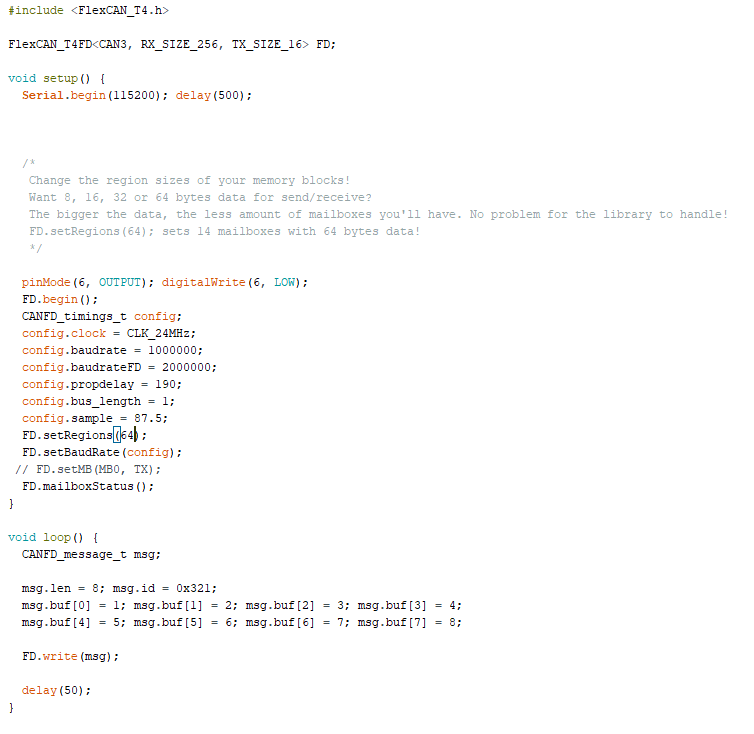
now my TX code is like that:
i added FD.enableMBInterrupts(); inside setup of TX, but does not make any change.
and RX code:
and on the serial monitor just a white screen
i removed CANFD_message_t msg; from inside loop() but also does not make any change.
Is there anything else that may be i did wrong !
Is your transceiver enabled? If not you need to drive the line LOW to enable it
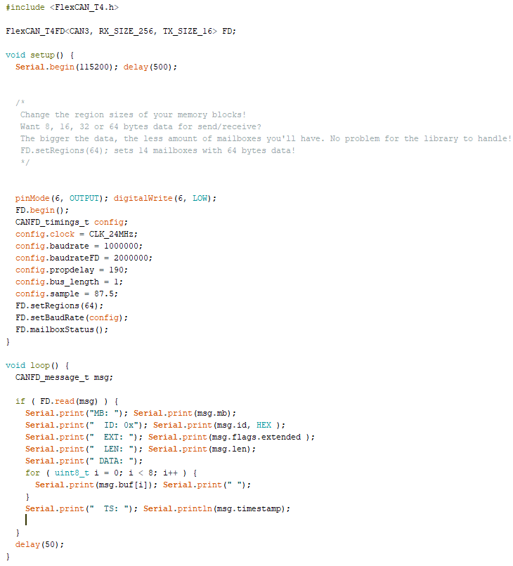
ALSO, begin() MUST be called BEFORE any other FD. calls, thats why it's blank because you didn't call begin to initialize the registers
Hint, look at onReceive and enableMBInterrupts
i will check that again tomorrow because i leaved now then i will back another hint; what do you mean by drive the line low, i think the UART take control of all pins after serial.begin(), or do you mean something else !
The transceiver enable pin, dont know if yours has one or not, didnt have time to check the datasheet of it, but for sure begin() has to be absolutely called first before the rest
no my transciever does not have enable pin. tomorrow i will check again the code, thanks Sir
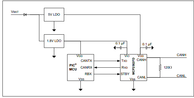
This is my transciever MCP2562FD from microship
Hi, i modified the code as you mention, and now i got the old output again.
i really wondering why it does not work! should i replace the transceiver with another type.
also i disconnect the transceiver and connect the rx and tx pins 30 and 31 for teensy on the oscilloscope and i got signal
Check if the transceiver CANH and CANL lines are parallel between each Teensy, and that both Teensies share a common ground path
Did you get up and running in CANFD mode yet? I've posted examples of TeensyCAN running CANFD in 8Mbps mode talking between nodes, perhaps you can use that to rule out software issue to check the wiring setup
Hi, i am not expert of teensy and i was excited to use its CANFD but i got upset. i set two nodes (TX and RX), i am using MCP2562FD transceiver, i uploaded the example for the two board without any problems, but i got nothing on the can line, also i got nothing on the serial monitor. i am working for 3 days on that and i could not find where is the problem, i review the wiring many times and its look like right, did i forget something ! or someone faced the same issues before ! This is what i see on the serial monitor of the receiver
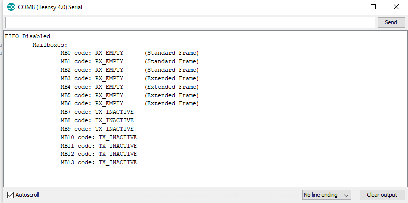
i used this code for receiving
and this for transmitting
i followed this diagram for wiring, but i connected STBY pin of the transceiver just to the ground!