Complementary note, the device appear not to be seen in the devices list :

Closed ronan-fontenay closed 2 years ago
Complementary note, the device appear not to be seen in the devices list :

If you use just unmodified TemperatureMonitor example, it should work. Then one possibility is that it does not response well for request. There should be also interrupt pin so you could enable it by #define N2k_CAN_INT_PIN xx.
If you read real temperture data from some sensor, then you have to take care that reading of sensor does not stop loop process. E.g. 1-wire temperature sensors default readers stops loop for up to 700 ms, so NMEA2000.ParseMessages will not be called fast enough. One must use asynchronous reading in those cases. So check that reader library will not have any delay call.
Hello, Thanks for the quick feedback.
I can confirm than I've used the original TemperatureMonitor / WinMonitor examples, with only one modification :
I've added the following line :
#define N2k_SPI_CS_PIN D10"
Just before :
#include <NMEA2000_CAN.h>
OK for the way forward, I'll try the TemperatureMonitor and add the interrupt pin definition (according to the Wemos/Lolin D1 R1 pintout, it should be D0). I'll need to go on board for this test, I'll do it asap.
#include <Arduino.h>
#define N2k_CAN_INT_PIN D0
#define N2k_SPI_CS_PIN D10
#include <NMEA2000_CAN.h>
Any suggestion to check if the interrupt is working well to validate the pin ?
Thanks again.
I tried to go further on this issue, without many success, my I've collected some information that might help.
1 - Hardware check
Status OK with the examples from CAN_BUS_Shield-master
Details
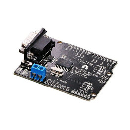
I changed hardware by 2 MCP2515 drivers (see picture). 120Ohms jumper set.

Basic check done with the following. Wemos1 : Examples > CAN_BUSShield-master -> send.ino (with const int SPI_CSPIN = D10;) Wemos 2 : Examples > CAN_BUS_Shield-master -> receivecheck (with const int SPI_CSPIN = D10;)
Result : The Wemos2 is well receiving data :
Get data from ID: 0
0   0   0   0   0   0   27  10
-----------------------------
Get data from ID: 0
0   0   0   0   0   0   27  11
-----------------------------
Get data from ID: 0
0   0   0   0   0   0   27  12
-----------------------------
Get data from ID: 0
0   0   0   0   0   0   27  13
2 - Tests done with the 2 boards setup
2.1 - Test 1 Wemos1 : TemperatureMonitor With the following changes :
#define N2k_CAN_INT_PIN D5
#define N2k_SPI_CS_PIN D10    // Pin for SPI select for mcp_can
#define USE_MCP_CAN_CLOCK_SET 8  // Uncomment this, if your mcp_can shield has 8MHz chrystal
...
Serial.begin(115200);
NMEA2000.SetForwardStream(&Serial);
...
NMEA2000.SetForwardType(tNMEA2000::fwdt_Text);
Wemos 2 : Datadisplay2 With the following changes :
#define N2k_SPI_CS_PIN D10    // Pin for SPI select for mcp_can
#define N2k_CAN_INT_PIN D2   // Interrupt pin for mcp_can
#define USE_MCP_CAN_CLOCK_SET 8  // Uncomment this, if your mcp_can shield has 8MHz chrystal
Results on Wemos1 :
CAN device ready
Start address claim for device 0
308 : Pri:6 PGN:60928 Source:22 Dest:255 Len:8 Data:69,B6,1,FF,0,82,96,C0
559 : Pri:7 PGN:126993 Source:22 Dest:255 Len:8 Data:60,EA,0,FF,FF,FF,FF,FF
2809 : Pri:5 PGN:130312 Source:22 Dest:255 Len:8 Data:1,1,4,7D,73,FF,FF,FF
2809 : Pri:5 PGN:130311 Source:22 Dest:255 Len:8 Data:1,C4,7D,73,FF,7F,FF,FF
Results on Wemos2 :
CAN device ready
Running...
2.2 - Test 2 Wemos 1 : MessageSender With the following changes :
#define N2k_SPI_CS_PIN D10    // Pin for SPI select for mcp_can
#define N2k_CAN_INT_PIN D2   // Interrupt pin for mcp_can
#define USE_MCP_CAN_CLOCK_SET 8  // Uncomment this, if your mcp_can shield has 8MHz chrystal
Results on Wemos1 :
CAN device ready
Start address claim for device 0
Starting message sender!
  Message sending to bus starts in 10 seconds.
  Type ?<lf> for available commands.
PGN 127493 send failed
PGN 127489, frame:0/4 send failed
PGN 130310 send failed
PGN 130311 send failed
PGN 127245 send failed
PGN 127250 send failed
PGN 127488 send failed
PGN 127493 send failed
PGN 127245 send failed
PGN 127250 send failed
PGN 127488 send failed
PGN 127493 send failed
PGN 129026 send failed
No more ideas at this stage, any suggestions ?
Thanks !
There is a voltage issue in this setup : Wemos is 3.3v, the MCP2515/MCP2551 5v. I switch to an ESP32 / Level shifter / MCP2551 setup.
For information, perfectly running with ESP32 / Level shifter (sparkfun) / MCP2551 !

In my document https://github.com/ttlappalainen/NMEA2000/blob/master/Documents/Connecting_hardware_to_NMEA2000.pdf "4.2.1 Recommended hardware" I have recommeded to use MCP2562 or ISO1050. Never had problems with those.
1 - Short description
Expected behavior : Using WindMonitor / TemperatureMonitor from examples, we should see wind / temperature data displayed on the lowrance HDS.
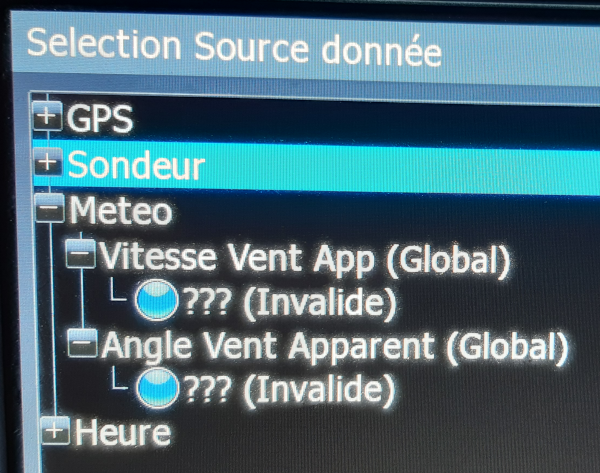
Actual behavior : The emulated devices seem to be recognized (new meteo data source shown on HDS) but the data appears to be "invalid".
Sorry for the pictures quality, I only had a poor smartphone on board with low lights these days.
2 - Details
2.1 - Hardware
Hardware is a Wemos D1 + Can Bus shield from Elecfreaks.

2.2 - Software
The software part is done by using examples as peer mentioned in the user guide.
The only modification is the declaration of the N2k_SPI_CS_PIN such as :
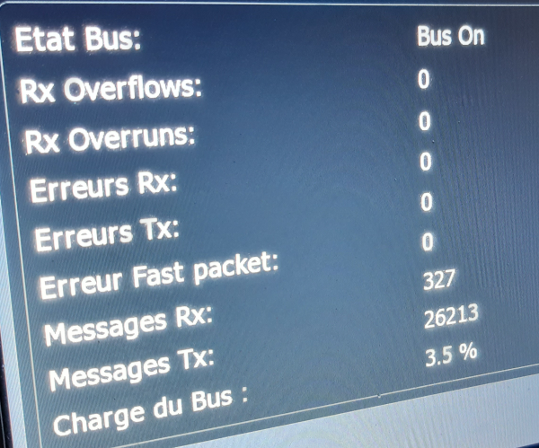
With no more data displayed. Bus seems OK (no packets errors shown on the HDS).
2.2.1 - WindMonitor / TemperatureMonitor
Device is seen on the HDS with invalid data.
I can see the RX value increasing on the bus statistics while the program is running, so packets are effectively sent on the bus.
2.2.2 - DeviceAnalyzer
Result of a message
So the can controller is well initialized, but not much information about why I don't see nothing more. We know that the HDS is at least sending GPS data on the N2K bus because the VHF is using them successfully.
Thank you for the huge work done here. I'm quite new to NMEA, I hope I didn't miss anything obvious.