wokwi / avr8js

Arduino (8-bit AVR) simulator, written in JavaScript and runs in the browser / Node.js
https://blog.wokwi.com/avr8js-simulate-arduino-in-javascript/
MIT License
461 stars 73 forks source link

How to set analog values? #128

Closed pfichtner closed 1 year ago

pfichtner commented 1 year ago

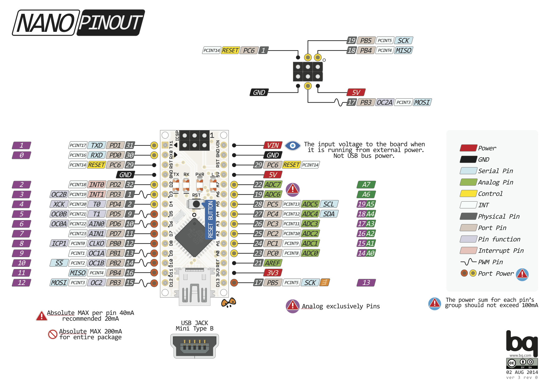
I am working on https://github.com/pfichtner/virtualavr

I found how to set the values of the digital pins: https://github.com/wokwi/avr8js/blob/8999cbc8f6df0d0f2cabfb54da1d8d059837b746/src/peripherals/gpio.ts#L334 How can I set values for analog pins?

urish commented 1 year ago
  1. Make sure you create an AVRADC device (e.g. const adc = new AVRADC(cpu, adcConfig);)
  2. Set adc.channelValues to the relevant voltage (between 0 and 5). For more advanced use cases, you can also override adc.onADCRead.

Checked your virtualavr project, that's a really neat use case! How did you find out about avr8js? and what makes it a good fit for you?

pfichtner commented 1 year ago

Great, that worked again :smiley: But directly afterwards the next question arises for me: How do I know if an analog pin value is set? For digital pins I can register listeners on portB https://github.com/wokwi/avr8js/blob/8999cbc8f6df0d0f2cabfb54da1d8d059837b746/src/peripherals/gpio.ts#L301 how to do for analog pins? I tried same for portC (and all others) but the listener's callback didn't get called when setting analog values.

I found avr8js because I stumbled over wokwi some weeks ago. My first try for my project was using simavr, Avr8js makes a good fit since it seems to be very easy to hook into internals like faking pin states e.g. and getting informed if pins states change but also all other hardware events.

urish commented 1 year ago

Hi Peter,

Glad to hear that it worked!

The ATMEGA328p chip doesn't have a built-in DAC, so there's no true analog write. Instead, Arduino's analogWrite function uses the timer to set up a PWM signal when you call analogWrite.

There are at least two different ways to "listen" for this:

  1. You can use the standard port listeners, and they should get called many times with high/low. What you are seeing is the digital PWM signal. Here's a video where I explain this: https://www.youtube.com/watch?v=7KYzPJ-tQno (and the relevant code example). That's the "official" method.
  2. You can also look directly at the timer registers (OCR0A, OCR0B, etc) and read the analogWrite value from them. If you look at the analogWrite() source code, you'll see it writes the given value directly to one of the OCR registers, depending the pin the user selected.
pfichtner commented 1 year ago

Thank you @urish , thanks for avr8js in general and your fast and qualified answers! I will have a look on it.

pfichtner commented 1 year ago

Great video @urish, thanks for that! I am little bit confused now.

when reading analog values on the arduino using
int a0 = analogRead(A0); I get the value 42 I set before in the simulator using adc = new AVRADC(cpu, adcConfig); adc.channelValues[0] = 42;

I guess those adc channels are the analog ports A0, A1, A2, A3, A4, A5, A6, A7 (see https://simba-os.readthedocs.io/en/15.0.1/_images/arduino-nano-pinout.png or https://www.arduino.cc/en/uploads/Main/ArduinoNanoManual23.pdf)

Doesn't the things you described in your video apply to the digital ports with pwm support D3, D5, D6, D9, D10 and D11 or also the analog ports A0-A7?

So my question is: As mentioned above I can read those analog ports A0-A7 on the "Arduino side". Can I see the writes to them made by the Arduino as well? If yes: On which port do I have to register a listener?

Thank you!

urish commented 1 year ago

I guess those adc channels are the analog ports A0, A1, A2, A3, A4, A5, A6, A7

That's correctly.

Doesn't the things you described in your video apply to the digital ports with pwm support D3, D5, D6, D9, D10 and D11 or also the analog ports A0-A7?

Only the the digital ports with PWM support. The name of the analog port is a bit misleading. They are actually digital ports which are also connected to the ADC (Analog to Digital converter). They do not have hardware PWM support, nor true analog output (DAC).

Can I see the writes to them made by the Arduino as well? If yes: On which port do I have to register a listener?

A0 through A5 are available on PORTC (pins 0 through 5). The A6/A7 pins are not connected to any digital port, only to the ADC, so you can't digitally read from them or write to them.

pfichtner commented 1 year ago

Thank you very much for the clarification @urish. I'll try to integrate it into my project and respond if I got it.

pfichtner commented 1 year ago

At the moment I am not using the Runner abstraction but creating cpu and ports by myself.

const cpu = new CPU(new Uint16Array(progData.buffer));
const adc = new AVRADC(cpu, adcConfig);
const portB = new AVRIOPort(cpu, portBConfig);
const portC = new AVRIOPort(cpu, portCConfig);
portB.addListener(() => console.log("portB"));
portC.addListener(() => console.log("portC"));

However, portC listener doesn't get called when doing analogWrite(A0, cnt++) while portB listener gets called on digitalWrite(LED_BUILTIN, LOW) (if portB's value has changed)

I guess did something wrong what AVRRunner is doing correctly. Will have to investigate later.

pfichtner commented 1 year ago

I forked your example code and tried to do the same on pin A0 you did on pin 11 (and removed those two unused leds): https://stackblitz.com/edit/avr8js-pwm-5lkaye It seems that the listener gets called much too seldom So I guess it's not a problem caused by not using the Runner abstraction but on the callback/listener behavior for portC.

urish commented 1 year ago

It seems that the listener gets called much too seldom So I guess it's not a problem caused by not using the Runner abstraction but on the callback/listener behavior for portC.

The thing is, A0 pin does not have hardware PWM on it. So calling analogWrite(A0, value) is the equivalent of calling digitalWrite(A0, value > 127 ? HIGH : LOW);.

You can actually see the code in the Arduino wiring library that implements this behavior: https://github.com/arduino/ArduinoCore-avr/blob/6154b7a7c1fba34737562aa4c29cec7451a82989/cores/arduino/wiring_analog.c#L276-L282

pfichtner commented 1 year ago

Thanks for clarification @urish, I guess this is equivalent for pins A1 to A7. So I don't understand why those pins are called analog ports? Wht makes them analog? Until now I thought digital pins can have values of 0V or 5V (and some of them can "simulate" values in between by doing pwm) and analog pins can have real values in between. Now you told me, that (at least) A0 has the behavior of an non pwm digital port. Did I understand correctly?

urish commented 1 year ago

Did I understand correctly?

Yes

So I don't understand why those pins are called analog ports?

I agree the name is misleading. A better name would have been "analog input pins".

pfichtner commented 1 year ago

Thanks for your support @urish! Got it working now! :smile: What else I stumbled across was that the resolutions of analogWrite and analogRead are different. After realizing this everything works like expected.