xoseperez / espurna

Home automation firmware for ESP8266-based devices
http://tinkerman.cat
GNU General Public License v3.0
2.99k stars 636 forks source link

Air quality sensor JQ-300 request #1644

Open fastjack opened 5 years ago

fastjack commented 5 years ago

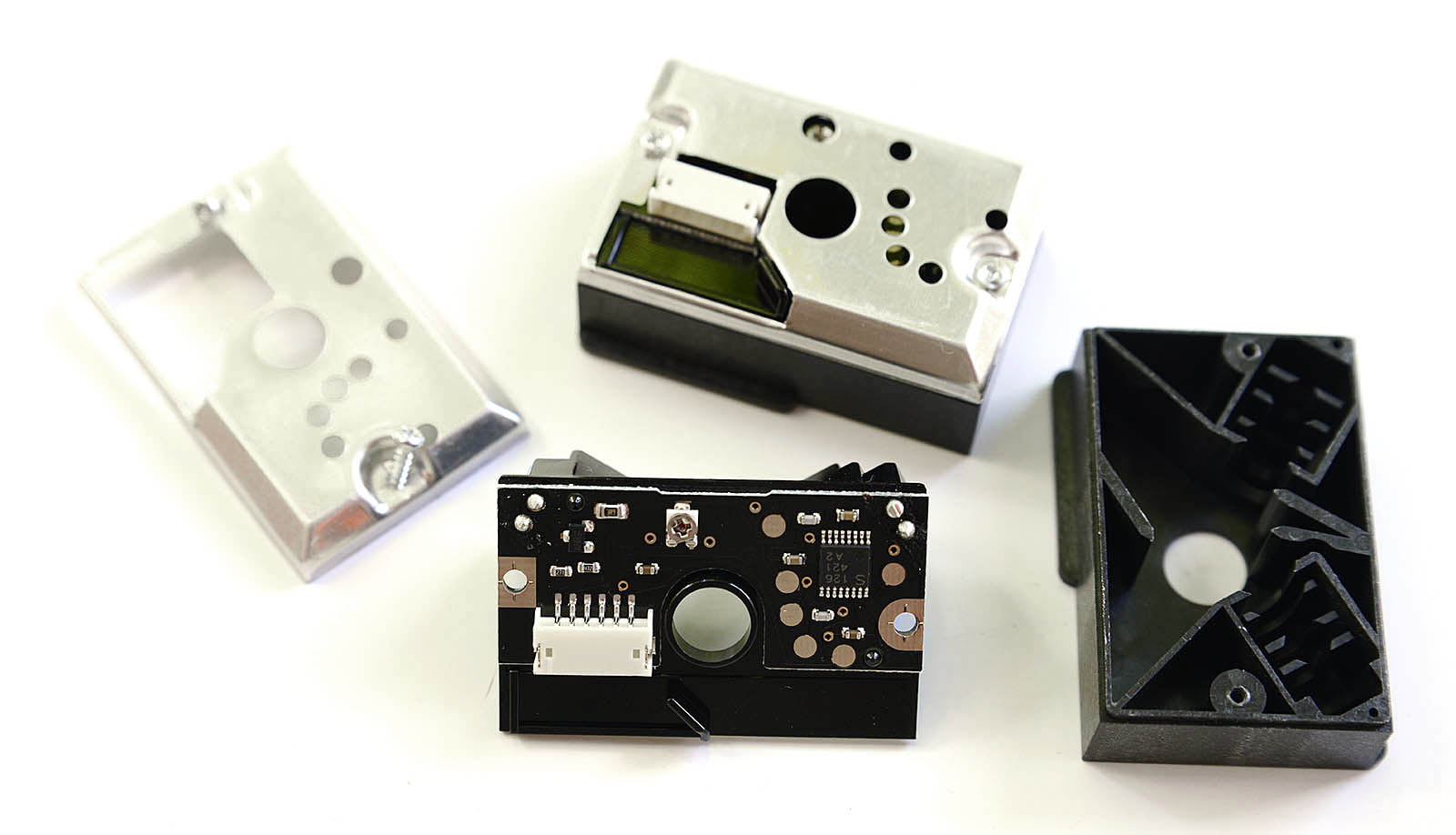
I found a chinese air quality sensor on Aliexpress. There doesn't seem to be a manufacturer associated with it. The device is simply called JQ-300. It contains an ESP-8266 and what looks like a SHARP GP2Y1010AUF0F (looks very similar to the dust sensor in the Sonoff SC)

I have attached pictures of the board and sensor.

2B54B191-F1CE-4B11-B007-CB088FA2ED59 2072FF90-DA44-46A2-BA56-BD8BC4FC594B CCA5F0F2-9C02-42CC-BFF9-4508EFE809A6 CF6162BF-F2CE-46AC-A60B-F7A306B6A72B

ZdenekM commented 5 years ago

@fastjack I'm about to buy one - have you tried to figure out how it communicates? It would be great if you can provide dump from WireShark or something like that. I was not able to find something usable about its protocol...

fastjack commented 5 years ago

@ZdenekM I haven't tried reverse-engineering its protocol because I don't care about that. Once it's running ESPurna (or some other custom firmware) I don't intend to keep it sending data to the (chinese) cloud.

SugoiDev commented 5 years ago

@fastjack Do you know of any custom firmware that could possibly run on this board? I'm also interested in no longer sending data away like it is doing now.

amimichael commented 5 years ago

I do not understand how you prepare the data to get to the UUID. 2F6E28F52248B028FFFF4F36D15125A4CD222603856E2F5EF07B#487f4d81 ypyt_mqtt_server2F6E28F52248B028A6B8C1E18CC3603095631ACEBB087769F204A744C1AF7B5F9E5CC324B162CFF91AF55DB8845F0F444E973287EBB0F45D#cfa0dff8 What does the URL for retrieving my data look like?

amimichael commented 5 years ago

Ok, I've come here so far.

http://www.youpinyuntai.com:32086/ypyt-api/api/app/deviceManager?platform=android&uid=8344&clientType=2&safeToken=7665895BDF40433AACC0A66443E16BAF&action=deviceManager

How do I get a list of the collected data?

amimichael commented 5 years ago

One must take the trouble to solder out the memory chip, read out and change the address of the cloud. @fastjack Hallo Herr Nachbar , interresse daran das mal offline zu diskutieren?

amimichael commented 5 years ago

@ZdenekM Wireshark Protocol

mitschnitt.txt change txt in pcapng

1234.txt

psghgv commented 5 years ago

@ZdenekM JQ300-filter IPnr-2.pcapng.txt Old Capture JQ-300 -<-> Internet

fastjack commented 5 years ago

One must take the trouble to solder out the memory chip, read out and change the address of the cloud. ...

@amimichael Hallo Nachbar, kein Problem. Meine Email-Adresse findest du in meinem Github-Profil

Sent with GitHawk

amimichael commented 5 years ago

Ich habe mich mit dem AIR-Q Hersteller geschrieben, er meint : Hallo Michael, auf der Leiterplattenoberseite sehe ich den Temperatur- und Luftfeuchtesensor oben links auf der kleinen Halbinsel. Rechts daneben mit den kreisförmig angeordneten Löchern ist wohl der VOC-Sensor. Der reagiert auch auf Formaldehyd, aber leider auch gleichtzeitig auf schlechten Atem und sonstige Ausgasungen, so dass man nicht sagen kann, ob wirklich eine gesundheitliche Belastung vorliegt. Vermutlich gibt er er als Formaldehyd den mit einem Faktor multiplizierten Wert von VOC aus. Dieser Sensor gibt noch eCO2 aus, also einen Wert, den CO2 haben müsste, wenn der gemessene VOC-Wert von menschlichen Ausdünstungen stammt - das stimmt nie. eCO2 anzugeben ist unserer Meinung nach Betrug am Kunden, weil hier eine Gewissheit vorgegeben wird, die nicht zutrifft.

I wrote to the AIR-Q manufacturer, he says hello Michael, On the upper side of the PCB I can see the temperature and humidity sensor on the top left of the small peninsula. Right next to it with the circular holes is probably the VOC sensor. The responds to formaldehyde, but unfortunately also at the same time on bad breath and other outgassing, so that one can not say whether there is really a health burden. Presumably he gives it as formaldehyde multiplied by a factor of value of VOC. This sensor still emits eCO2, a value that CO2 would have to have if the measured VOC value came from human fumes - that's never true. eCO2 is in our opinion fraud on the customer, because here a certainty is given, which does not apply.

zerog2k commented 5 years ago

Hi folks, I was also interested in these units for a pre-made AQ sensor. (I am now a bit disappointed in how they have built the hardware). Sharing a few random observations:

hardware

software

communication protocols

My hope was to reverse engineer this and write some script where I could just receive the data myself. However, due to the way they are dumping the device messages into a single big queue (rather than leveraging a topic naming hierarchy scheme, like device/{ID} where you could listen to all devices devices/#, or just one device) - for this reason I would not recommend dumping their mqtt streams for long - it's alot of data, and you might get flagged/blocked, if they are smart enought to have rate limiting. Also, sadly, while the device serial output shows the device id, but does not show the device key, so I was hoping to find some way of determining the key without dumping the flash. The only other way I see is to force factory re-provisioning (requires you to have some wifi ssids of "ypyttest1" and/or "ypyttest2" ready for device to connect to), then you can watch both serial output, and look for initial provisioning message (encrypted with master key) on cloud mqtt.

I think best plan is to reverse the esp to sensor mcu comms and find out a way to load custom firmware on the esp (although this would likely be only for advanced users due to desoldering of flash or mcu)

SugoiDev commented 5 years ago

Outstanding work, @zerog2k! I had previously investigated the mqtt implementation, but got nowhere close to what you got.

My initial idea was to replace it's remote server with a rogue local one and route all the data to a local machine, but I failed to parse the payload's contents. It's much clearer now, with your investigations!

zerog2k commented 5 years ago

Ok, I thought about this a bit more, and I think there are a few possibilities both with existing cloud (without using crap app) or without cloud (you somehow redirect the mqtt traffic to your own server [i.e. iptables, dns, etc])

First a bit about the initial provisioning (factory test) mode, which I think makes it possible to monitor via cloud. The idea here is that you can bypass the need of the app to setup the device and bind to cloud, and discover the application id (app_num_user ?) which is the topic you can subscribe to to get the cleartext json output of the device (what the app would see from the cloud).

The factory test/init process seems to go something like this:

now device seems to disconnect from initial provisioning topic, Jyyyyyyyzzzzzz, and now listens to topic aaaaaaaaaaaaaaaa from here on, the encryption key used for all payloads is the device pkey negotiated above and encrypted device messages to ypyt_bingding_topic are prefixed w/ device id instead of FFFF (see encryption notes below).

from here seems to be basically repeating loop of device sending in data, with cloud ack'ing it, and sometimes some other control messages/heartbeats infrequently, e.g.:

this mostly repeats forever

Another interesting aspect is how to get the device to connect to a wifi network without the crap phone app. You can use an ESP Smart Config app like DoIt's Esptouch or Espressif's Esptouch app, which will send wifi credentials to the app (via some udp/wifi frame broadcast magic voodoo). However, these devices need the password to be appended with some special magic token string (u9i9d9nnnn), where nnnn is some number (seems to be related to the E30015FFaaaaaaaaaaaaaaaa#nnnn message above?) i.e., if your wifi is "password", you need to enter "passwordu9i9d9nnnn"

So theoretically, it's possible to (re)provision the device in order to get the pkey, such that you can get the deviceToken to monitor the device data, or perhaps we can just bypass the cloud mqtt and re-route to our own mqtt server, and fake the cloud?

A few other interesting observations about encryption:

zerog2k commented 5 years ago

The slight downside with factory re-provisioning w/ cloud is that everyone listening can determine what your device id and pkey are now. (I'm not sure if there are nefarious things you can do if you know a particular device's pkey, like reset wifi credentials [knocking it offline] or maybe worst case, some OTA update)

The other option is to dump the flash of existing unit and you can get your id/key.

I have an example python script which will take this device token, listen to the mqtt topic, parse, and print out the sensor data. No need for app: https://gist.github.com/zerog2k/b3afcaf3ff92a60474a159c7044dc8ce

Sat Jun  1 11:10:34 2019
message: sensor values
temp    21  C
hum     58  %
PM2.5   33  ug/m^3
HCHO    0.005   mg/m^3
TVOC    0.322   mg/m^3
eCO2    645     ppm

however, the data only as good as this device/cloud, i put it side by side with a Nordic Thingy (which also outputs TVOC, eCO2, etc) which seems to be slightly different on a few values, and not sure about the eCO2 and TVOC... (I think I would trust the Nordic design/quality better ;)

developer-ids commented 5 years ago

Easy way to get the device id:

  1. Pair the app with the device.
  2. TcpDump the connection from app to cloud (mq.youpinyuntai.com:55450)
  3. look from MQTT subscribe from app. with that id you can use any mqtt client to see the values.
lucamot commented 5 years ago

I found out that the app makes HTTPS request to get the data in JSON format. Capturing traffic of it I found this is the request to look for:

https://www.youpinyuntai.com:31447/device/list?deviceToken=XXXXXXXXXXXXXXXXXXXXX&saveToken=SSSSSSSSSSSSSSSSSSSSSSSSSSSSSSSS&uid=8228&timestamp=1557220969315&tz=-2&type=1&page=0&&callback=jsoncallback&_=TTTTTTTTTTTTT In particular, the device token (marked with X) and the _ parameter (marked with T) should be replaced with the real device token and the unix timestamp of the date when making the request (i.e. date "+%s on a linux machine). The S token is constant for me (I have 2 devices) but it might be a unique id for my application.

The JSON response is something like this:

{"returnCode":"0000","returnMsg":"成功","timestamp":0,"deviceValueVos":[{"content":"0","dptId":1,"seq":1},{"content":null,"dptId":1,"seq":2},{"content":null,"dptId":1,"seq":3},{"content":"26","dptId":1,"seq":4},{"content":"55","dptId":1,"seq":5},{"content":"33","dptId":1,"seq":6},{"content":"0.001","dptId":1,"seq":7},{"content":"0.220","dptId":1,"seq":8},{"content":"375","dptId":1,"seq":9},{"content":null,"dptId":1,"seq":10}],"deviceToken":"XXXXXXXXXXXXXXXXXXXXX"}

The response is quite simple and contains an array (deviceValueVos) with a seq parameter inside each element. The seq parameter seems to identify the read value following this table

4 -> Temperature 5 -> Humidity 6 -> PM 2.5 7 -> HCHO 8 -> TVOC 9 -> eCO2

I currently have a simple BASH script that uses CURL to fetch these info every 5 minutes without the use of the app.

djbios commented 5 years ago

I found out that the app makes HTTPS request to get the data in JSON format. Capturing traffic of it I found this is the request to look for:

https://www.youpinyuntai.com:31447/device/list?deviceToken=XXXXXXXXXXXXXXXXXXXXX&saveToken=SSSSSSSSSSSSSSSSSSSSSSSSSSSSSSSS&uid=8228&timestamp=1557220969315&tz=-2&type=1&page=0&&callback=jsoncallback&_=TTTTTTTTTTTTT In particular, the device token (marked with X) and the _ parameter (marked with T) should be replaced with the real device token and the unix timestamp of the date when making the request (i.e. date "+%s on a linux machine). The S token is constant for me (I have 2 devices) but it might be a unique id for my application.

The JSON response is something like this:

{"returnCode":"0000","returnMsg":"成功","timestamp":0,"deviceValueVos":[{"content":"0","dptId":1,"seq":1},{"content":null,"dptId":1,"seq":2},{"content":null,"dptId":1,"seq":3},{"content":"26","dptId":1,"seq":4},{"content":"55","dptId":1,"seq":5},{"content":"33","dptId":1,"seq":6},{"content":"0.001","dptId":1,"seq":7},{"content":"0.220","dptId":1,"seq":8},{"content":"375","dptId":1,"seq":9},{"content":null,"dptId":1,"seq":10}],"deviceToken":"XXXXXXXXXXXXXXXXXXXXX"}

The response is quite simple and contains an array (deviceValueVos) with a seq parameter inside each element. The seq parameter seems to identify the read value following this table

4 -> Temperature 5 -> Humidity 6 -> PM 2.5 7 -> HCHO 8 -> TVOC 9 -> eCO2

I currently have a simple BASH script that uses CURL to fetch these info every 5 minutes without the use of the app.

Can you share your script?

vologab commented 5 years ago

@djbios My script is:

#!/bin/bash

timestamp=$((`date +%s` - 300))000;
request_url="https://www.youpinyuntai.com:31447/device/list?deviceToken=0DBB2CC60249A12B9000&saveToken=0062243D213348B2B5B249C92BA6000C&uid=3597&timestamp=${timestamp}&&callback=jsoncallback&_=${timestamp}";
curl -ks ${request_url} | sed -E "s/jsoncallback\((.*)\)/\1/g" | jq --arg timestamp "${timestamp}" -r '.deviceValueVos | reduce .[] as $item (""; . + "," + ($item.content|tostring) + "," + ($item.dptId|tostring) + "," + ($item.seq|tostring)) | .+","+$timestamp' >> /home/pi/data/air_sensor/air_sensor_data.csv
djbios commented 5 years ago

@djbios My script is:

#!/bin/bash

timestamp=$((`date +%s` - 300))000;
request_url="https://www.youpinyuntai.com:31447/device/list?deviceToken=0DBB2CC60249A12B9712&saveToken=0062243D213348B2B5B249C92BA6A84C&uid=3597&timestamp=${timestamp}&&callback=jsoncallback&_=${timestamp}";
curl -ks ${request_url} | sed -E "s/jsoncallback\((.*)\)/\1/g" | jq --arg timestamp "${timestamp}" -r '.deviceValueVos | reduce .[] as $item (""; . + "," + ($item.content|tostring) + "," + ($item.dptId|tostring) + "," + ($item.seq|tostring)) | .+","+$timestamp' >> /home/pi/data/air_sensor/air_sensor_data.csv

Unfortunately, this not works for me. I'am getting jsoncallback({"returnCode":"0101","returnMsg":"您的账号已在其它地方登录","timestamp":0}) I've used deviceToken, saveToken and uid from mobile app request. And in my request "saveToken" was called "safeToken", but neither works.

UPD: Somehow deviceToken was changed. I've updated it by curl "www.youpinyuntai.com:32086/ypyt-api/api/app/deviceManager?uid=9923&clientType=2&safeToken=39D03B113FF042E6A8D70F0E2835E218&action=deviceManager", and now it works

tutupmulut commented 4 years ago

@djbios you have to change the “deviceToken=“ , “saveToken=” and “uid=“ values to match your device.

jrmacleod commented 4 years ago

I successfully created a PHP script that every minute via a cron job would pull the JSON via CURL to get the latest sensor values for my given device ID, used ID and save token.

However now it always is getting identical values every time it requests the data.

I notice by packet sniffing of the perthings app it looks like its JSON requests also always gets the same data back but mqtt requests (I think) are getting updated sensor values every few seconds.

Any idea why? Also can I use CURL to poll MQQT values rather than an MQQT client? I have curl setup nicely from PHP code to poll my multiple devices in parallel which makes the script very efficient, and am not familiar with using mqtt clients.

Any insight would be appreciated!

jmw6773 commented 4 years ago

Does anyone know if there been any work on decoding the serial RX/TX between the ESP8266 and the other MCU inside of the device that is connected to all of the sensors? I'd really like to get this device off of the Internet and keep it intranet.

I suck at reverse engineering signals, but the nearest I can tell is that its a serial packet of 15 HEX values with the structure below. The temperature and humidity match what the app gives, but it seems odd do me that it would be calculations on the hex values though.

   HEAD     ALERT         ???        TEMP     HUM      PM2.5    TAIL
59 50 FE    00        18 95 18 78    45 00    31 00    33 70    F0

ALERT - seems to be set to 02 when values are considered dangerous Temperature (in C) = TEMP - 12 (33C = 45 - 12) Humidity= HUM + 24 (55% = 31 + 24) ??? = I haven't figured out the structure for the CO2, HCHO, TVOC values PM2.5 = Only these values (and ALERT) change when the PM2.5 sensor is disconnected

lucamot commented 4 years ago

@jrmacleod this happens to me too: it happened in the past too, but it seems to be something related to their server. I don't know if it's a maximum requests cap they have or anything else, the last time I reset several times both devices and it worked again.

This time I'm going to wait for the data to be back in sync on their servers, let's see what happens!

lucamot commented 4 years ago

Does anyone know if there been any work on decoding the serial RX/TX between the ESP8266 and the other MCU inside of the device that is connected to all of the sensors? I'd really like to get this device off of the Internet and keep it intranet.

I suck at reverse engineering signals, but the nearest I can tell is that its a serial packet of 15 HEX values with the structure below. The temperature and humidity match what the app gives, but it seems odd do me that it would be calculations on the hex values though.

   HEAD     ALERT         ???        TEMP     HUM      PM2.5    TAIL
59 50 FE    00        18 95 18 78    45 00    31 00    33 70    F0

ALERT - seems to be set to 02 when values are considered dangerous Temperature (in C) = TEMP - 12 (33C = 45 - 12) Humidity= HUM + 24 (55% = 31 + 24) ??? = I haven't figured out the structure for the CO2, HCHO, TVOC values PM2.5 = Only these values (and ALERT) change when the PM2.5 sensor is disconnected

So I captured a few serial packet and here is what I think:

Now a few observations I have: it might be only on my device but that "1895 1878" is always in the form A B, where A and B are both 2 bytes in length and B is always smaller or equal to A. In fact, as soon as B reaches A, A is incremented by some quantities. This might be because those eCO2/TVOC/HCHO are all linked together, but still worth a note.

I was still not able to relate all the captures to the exact data that is sent to the cloud and I think those parameters are encoded in a way that could only be inferred by knowing the sensor used.

Anyone is able to identify those sensors so that we can lookup in the datasheets and see what format they use?

jmw6773 commented 4 years ago

@lucamot, Thank you for your reply and looking into this.

I also believe that the temperature and humidity are in HEX, like the rest of the packet. However, I wasn't able to get the values to correlate with the measured temperature in the app if I converted them to base 10. Adding the described decimal value to the HEX gave the same value in the APP for all values between 20-33C and 45-78% humidity. Still scratching my head on this one. I forgot about the calibration done in the APP for humidity, so the formula(s) should be changed for this.

My PM2.5 sensor looks the GP2Y1010AU0F The Temp/Humidity sensors looks like a HDC1080 chip.

I haven't been able to identify the MEMS chip that does the VOC, CO2, and HCHO sensing. The MEMS chip package that I have looks different than the image at the top of this thread. (More holes in the can.)

lucamot commented 4 years ago

Another update on this topic: I managed to dump the original firmware from the device (not the one shown on the picture above but the one on the new version of the board) and succeeded in flashing a custom firmware to the ESP (both Espurna and Tasmota, for the sake of curiosity). The operation seems quite complicated but it's easier than I thought since the RX pin is very accessible on the ESP8266 and the TX pin (the one associated with GPIO2) is linked to one of the test points on the board. Entering serial bootloader mode it's just a matter of shorting one of the pin of the blue/green led with the middle one (short the pin which is nearer to the ESP8266, it's connected to GPIO0).

The only thing I can confirm though is that every 3 seconds the ESP receives via UART rx pin the payload already mentioned in some posts above. The original firmware replies with the string "alldata_value_successful!\n" on the UART tx pin and then, after 40ms, it emits another string "device_request_server_all_data\n", again on the UART tx pin.

Unfortunately, I'm still not able to decode the string above to be used with different firmwares, if anyone has some ideas it's very welcome: my next though is to try to sniff the communication between the sensors and the MCU, but this might be a dead end since if the MCU re-encodes the values I might only have a mapping between values without knowing the real algorithm used.

ghost commented 4 years ago

You guys are way over my head but I can’t find any other place for help. I get hung up in the Perthings app at the time is says to “enter wifi name” so I enter my wifi name for 2.4 ghz wifi and hit next... and get an error of “please enter wifi name” I have rebooted phone, router and device... can’t get passed enter wifi name... any help would be hugely appreciated. TY.

AlexStOd commented 4 years ago

Hi all, I tried to decode temperature and humidity data and found the same results as jmw6773:

  1. All values are BCD, not usual hex. So value 0x30 means 30dec. The second byte is always 00 - fractional part is not used.
  2. Temperature is BCD - 12. So 16deg is 2800, 17deg is 2900, 18deg is 3000, 19deg is 3100, etc.
  3. Humidity behavior is strange. It is calculated by a perthings app as "hum = value +20" in range of value 0000...5900. But it is calculated as "hum = value" in range of value 6000...9900. So value 0000 is shown by app as 20%, value 3000 is shown as 50%, 5900 is shown as 79%, but 6000 is shown as 60%, 8000 is shown as 80%. Looks like it is a app problem because the measured value is monotonously growing with humidity, but represented value has a step. The second byte is always 00 too.
  4. PM2.5 data is in BCD format too. It varies in range 0000...3998. 0000 is if I short pins 4 and 5 and 3998 is if I short pins 5 and 6 of sensor. The value is also growing up to 3998 if I insert some pen in a sensor hole ))). I am wondering now how to make some predefined conditions to test MEMS sensor...
AlexStOd commented 4 years ago

As PM2.5 sensor is analog - I connected a potentiometer between pins 4 (GND), 5 (Vin), 6 (+5V) and tried to change voltage and see reported data. As I said before - data is BCD encoded too. And it represent a voltage at pin 5 (Vin). 0V = 0000, 1V = 1000, 2.5V = 2500, etc. Maximum measured voltage is 4V = 3998, any greater voltage is reported as 3999. Then I checked correspondence between voltage (or measured voltage) and PM2.5 value which is reported by Perthings application. Result: 0900 - 244 ug/m3 0770 - 200 ug/m3 0700 - 175 ug/m3 0630 - 150 ug/m3 0578 - 125 ug/m3 0500 - 100 ug/m3 0440 - 75 ug/m3 0380 - 50 ug/m3 0212 - 25 ug/m3 0190 - 16 ug/m3 0163 - 7 ug/m3 0150 - 5 ug/m3 0144 - 1 ug/m3 The values have some deviations, it is not clear why. But in average it is ok. All greater values are reported as ">250ug/m3", so it is wasn't possible to measure them.

cagnulein commented 4 years ago

Is there a simple way to get the token id from the Android app? Or i have to sniff the traffic?

jmw6773 commented 4 years ago

@AlexStankov

Could you clarify your results a little? Is the first value the measured Vin *100? (i.e. 1.5v on Vin pin = 0150) If so, could you confirm that you're getting 9v?

AlexStOd commented 4 years ago

Sorry, it's my fault. Range of 0V...4V is represented as 0000...3998. So 0900 means 0.9V.

jmw6773 commented 4 years ago

@AlexStankov Thank you for the explanation. That makes more sense.


I just noticed that the adjustment dial on my PM is in a different hole than what other GP2Y1010AU0F modules have. (The original post in this thread looks like mine.) You can also see resistors in the right 4 open holes. The GP2Y1010AU0F module doesn't have these resistors/caps.

I removed the back cover of my PM module and found a 2TY (PNP Transistor) a N81D (?), both in SOT-23, a 14-pin IC (the upper side has grooves in it, not sure if to remove all markings), and a boat load of resistors and capacitors.

Maybe our PM modules aren't Sharp, and don't follow the same dust curve as the GP2Y1010AU0F? Or maybe the modules aren't analog and are actually outputting a PWM signal like the GP2Y1023AU0F module?

Comparison: GP2Y1010AU0F My Module (Sorry for the potato quality)

AlexStOd commented 4 years ago

My sensor looks like your sensor. The chip is unmarked too. So looks like is it a Сhinese fake. I'll try to check the sensor behavior by oscilloscope.

yath commented 4 years ago

In case you’d like to reverse-engineer the firmware, I’ve written https://github.com/yath/ghidra-xtensa for the CPU but got stuck in provisioning mode and somehow forgot about it. I’ll try to reprovision it and/or try a different firmware to get an idea of the memory layout and how the other MCU’s data is processed, but I thought I’d share the processor module already.

AKuHAK commented 4 years ago

Hi guys. I understand that this topic is about raw hardware hacking, but I faced a problem with this device and the Chinese reseller cannot help me with it. The mentioned device (JQ-300) started blinking blue lights and doesn't connect to 'perthings' app anymore. I just want to ask maybe this is some kind of safe mode or factory mode, and maybe there is a simple way to return this device to work.

ghost commented 4 years ago

the blue mode is for pairing with bluetooth or pairing other then wifi... by ppressing and holding the button for 3 seconds and lettting go the light should cycle and then start green again.... if you hold button in to long like 7 second and then rel;ease you are entering a different pairing mode then wifi aqnd yess should see blue blinking. if pressing and holding for 3 or 7 second doesnt change the pairing mode... then sorry but i dont know anymore to help... good luck...

On Tue, Feb 4, 2020 at 7:17 AM AKuHAK notifications@github.com wrote:

Hi guys. I understand that this topic is about raw hardware hacking, but I faced a problem with this device and the Chinese reseller cannot help me with it. The mentioned device (JQ-300) started blinking blue lights and doesn't connect to 'perthings' app anymore. I just want to ask maybe this is some kind of safe mode or factory mode, and maybe there is a simple way to return this device to work.

— You are receiving this because you commented. Reply to this email directly, view it on GitHub https://github.com/xoseperez/espurna/issues/1644?email_source=notifications&email_token=AN4ABEOMXCMEMLEBFCJBF3LRBFMENA5CNFSM4HADPCDKYY3PNVWWK3TUL52HS4DFVREXG43VMVBW63LNMVXHJKTDN5WW2ZLOORPWSZGOEKXNQQQ#issuecomment-581883970, or unsubscribe https://github.com/notifications/unsubscribe-auth/AN4ABEMGFQQOHREHWDHMCE3RBFMENANCNFSM4HADPCDA .

AKuHAK commented 4 years ago

by ppressing and holding the button for 3 seconds and lettting go the light should cycle and then start green again.... On Tue, Feb 4, 2020 at 7:17 AM AKuHAK @.***> wrote: Hi guys. I understand that this topic is about raw hardware hacking, but I faced a problem with this device and the Chinese reseller cannot help me with it. The mentioned device (JQ-300) started blinking blue lights and doesn't connect to 'perthings' app anymore. I just want to ask maybe this is some kind of safe mode or factory mode, and maybe there is a simple way to return this device to work. — You are receiving this because you commented. Reply to this email directly, view it on GitHub <#1644?email_source=notifications&email_token=AN4ABEOMXCMEMLEBFCJBF3LRBFMENA5CNFSM4HADPCDKYY3PNVWWK3TUL52HS4DFVREXG43VMVBW63LNMVXHJKTDN5WW2ZLOORPWSZGOEKXNQQQ#issuecomment-581883970>, or unsubscribe https://github.com/notifications/unsubscribe-auth/AN4ABEMGFQQOHREHWDHMCE3RBFMENANCNFSM4HADPCDA .

Thank you this helped a lot! I didnt released before button after 3 seconds, now everything is fine.

ghost commented 4 years ago

good to hear. welcome. yes i had similar trouble with setup

On Thu, Feb 6, 2020 at 5:46 AM AKuHAK notifications@github.com wrote:

by ppressing and holding the button for 3 seconds and lettting go the light should cycle and then start green again.... … <#m6749222344186149057> On Tue, Feb 4, 2020 at 7:17 AM AKuHAK @.***> wrote: Hi guys. I understand that this topic is about raw hardware hacking, but I faced a problem with this device and the Chinese reseller cannot help me with it. The mentioned device (JQ-300) started blinking blue lights and doesn't connect to 'perthings' app anymore. I just want to ask maybe this is some kind of safe mode or factory mode, and maybe there is a simple way to return this device to work. — You are receiving this because you commented. Reply to this email directly, view it on GitHub <#1644 https://github.com/xoseperez/espurna/issues/1644?email_source=notifications&email_token=AN4ABEOMXCMEMLEBFCJBF3LRBFMENA5CNFSM4HADPCDKYY3PNVWWK3TUL52HS4DFVREXG43VMVBW63LNMVXHJKTDN5WW2ZLOORPWSZGOEKXNQQQ#issuecomment-581883970>, or unsubscribe https://github.com/notifications/unsubscribe-auth/AN4ABEMGFQQOHREHWDHMCE3RBFMENANCNFSM4HADPCDA .

Thank you this helped a lot! I didnt released before button after 3 seconds, now everything is fine.

— You are receiving this because you commented. Reply to this email directly, view it on GitHub https://github.com/xoseperez/espurna/issues/1644?email_source=notifications&email_token=AN4ABEO4MLYH6T7YR7UUBV3RBPTBRA5CNFSM4HADPCDKYY3PNVWWK3TUL52HS4DFVREXG43VMVBW63LNMVXHJKTDN5WW2ZLOORPWSZGOEK6YEJI#issuecomment-582844965, or unsubscribe https://github.com/notifications/unsubscribe-auth/AN4ABEOHCMXUZRXWN66TFULRBPTBRANCNFSM4HADPCDA .

bobas commented 4 years ago

Guys, there is an absolutely easy way to get the device id if you have a rooted phone with the Perthings app.

The device id is stored plain text in the app database. You can read the database with SQLite database editor (by Supertommino) from Google Play store. The Perthings app needs to be in device internal memory, not sd card (you can use Titanium backup to move it). Just open the editor, choose Perthings -> im.db and look for the mqttTopic record. You can copy it out to use with zerog2k's script (thanks a lot for it!!).

jovimon commented 4 years ago

Another update on this topic: I managed to dump the original firmware from the device (not the one shown on the picture above but the one on the new version of the board) and succeeded in flashing a custom firmware to the ESP (both Espurna and Tasmota, for the sake of curiosity). The operation seems quite complicated but it's easier than I thought since the RX pin is very accessible on the ESP8266 and the TX pin (the one associated with GPIO2) is linked to one of the test points on the board. Entering serial bootloader mode it's just a matter of shorting one of the pin of the blue/green led with the middle one (short the pin which is nearer to the ESP8266, it's connected to GPIO0).

The only thing I can confirm though is that every 3 seconds the ESP receives via UART rx pin the payload already mentioned in some posts above. The original firmware replies with the string "alldata_value_successful!\n" on the UART tx pin and then, after 40ms, it emits another string "device_request_server_all_data\n", again on the UART tx pin.

Unfortunately, I'm still not able to decode the string above to be used with different firmwares, if anyone has some ideas it's very welcome: my next though is to try to sniff the communication between the sensors and the MCU, but this might be a dead end since if the MCU re-encodes the values I might only have a mapping between values without knowing the real algorithm used.

Hey @lucamot, could you possibly explain in nore detail how were you able to dump the firmware, which test ports did you use, or even provide the firmware you dumped? I'm trying to extract the firmware but without luck so far. My board is exactly the same as the one photographed in the first post. Thank you very much.

JaneX8 commented 4 years ago

Oh, I would really like this thing reverse engineered for HASS.io integration and other thing. In fact after reading this issue I decided to buy a JQ-300 myself for doing some reverse engineering later myself.

Quite a scam. I bought a JQ-300 according to my order, it looks from the outside like a JQ-300 based on the English description manual (apparently only JQ-300 has the round airhole in the middle) and mine has also, but compared to the photos of the inside above and the device I have it's clearly lacking an pm2.5 sensor making it simply a JQ-200 instead. The package has three unchecked options for JQ-100, JQ-200 and JQ-300. And a JQ-200 sticker was added on the box as sealing. Funny thing is that when connected to the app it also shows it's a JQ-300 but it lacks the PM2.0 information entirely.

Also connecting it to the app didn't go without problems. I could not install the app from the play store on Android so I had to install a shady APK which was pointed out using a QR code on the package. The app did not work properly at all and could not determine my SSID so I was unable to pair the device to my network. Then on an iphone I could install it from the App Store and managed to finally bind the device to my account.

ckesc commented 4 years ago

BTW here's integration for HomeAssistant https://community.home-assistant.io/t/jq-300-200-100-indoor-air-quality-meter/189098

Stoatwblr commented 4 years ago

I wonder if this can be tasmotised?

Stoatwblr commented 4 years ago

which test ports did you use

Looking at the board photo:

GPIO0 is the letter B by the led. Short this to the centre to put the device in programming mode. (leave it there)

GPIO2 is the left hand thruhole land adjacent to "JQPM-1 V3.0" (the right hand one is ground) The track under the + is 3.3V (also top left pin of U6) the pin marked c is pin1 (numbering is counterclockwise)

GPIO4 appears to link to S1 (not connected) GPIO5 seems to go to the green led

Normally you'd use pins 25(rx) and 26(tx) for this job (bottom row of the ESP2566, left pair of pins), but these dive off under U5, emerging at U5 pin 11 and 12 respectively (13 goes to pin 32 on the ESP - RST). If you want to try bootloading using those pins I'd suggest pulling the Sharp sensor first and feeding in an external 3.3V supply, as it appears the UART has a separate feed from the 5V supply via U7

A lot of the time these blanked out chips have been painted over. I'm going to try an acetone attack and see if it helps identify the thing (EDIT: nope, acetone didn't work. These really do seem to be some kind of unbranded a/d converter)

Stoatwblr commented 4 years ago

the blue mode is for pairing with bluetooth or pairing other then wifi...

Actually it's for pairing with a "YPLINK hotspot" - SSID: aaa PASS: 12345678 (yeah, really secure)

I can make that work with my android on the perthings app, but it will not reset to the house wifi (perhaps because I have !"$%^&*()_=?+-<>@ characters in the password - they're US-ASCII and should be allowed but I've seen worse dainbramaged behaviour in the past)

EDIT: You can change the ssid and password for the AP in the Perthings app, but contrary to the instructions the light stays blue even if you pair it with your home AP. Setting it back into the flashing green pairing mode clearly isn't supported in the android app and will fail if you attempt to do so. It's working happily on my home Wifi in solid blue led mode (having set it away from ssid aaa) and seems to be phoning home

If you're uneasy about having a "rogue" device on your wifi then I suggest you do what i do and put it on the guest network (I have a Fritz Box, this has a guest WIFI SSID and guest LAN network). Due to widespread attacks on login/passwords you would be extremely silly to use a non-unique login/pass for the perthings cloud

Stoatwblr commented 3 years ago

Back on trying to hack into this thing and tasmotize it @lucamot - what pins were you using? The standard GPIO1/GPIO3 pair don't work

Leo-PL commented 3 years ago

I think that the sensor could be interrogated periodically on Tasmota with a simple rule, for example:

Rule1 ON Rules#Timer=1 DO Backlog SerialSend1 device_request_all_data ENDON ON SerialReceived#Data DO Backlog SerialSend1 alldata_value_successful!; RuleTimer1 3 ENDON
Rule1 1
RuleTimer1 3

Does anyone recall which baud is used on UART connection to external MCU? Tried that, but without correct baud, to no avail.

Leo-PL commented 3 years ago

Got some moderate success on Tasmota with this template:

{"NAME":"JQ-300","GPIO":[290,3200,1,3232,1,289,1,1,1,288,1,1,1,1],"FLAG":0,"BASE":18}

And the following configuration in console:

SerialConfig 8N1
Baudrate 230400
SerialDelimiter 255
Rule1 ON System#Boot SerialSend4 "device_request_all_data\n"
Rule1 on

Then after sending empty string, built-in MCU starts spewing out data - Not sure if the baud is still correct. Frames repeat every 3s, but vary with contents slightly:

13:53:21 RSL: tele/tasmota_8F0A5B/RESULT = {"SerialReceived":"8666660066987866187806180618661E00"}
13:53:21 QPC: Reset
13:53:25 RSL: tele/tasmota_8F0A5B/RESULT = {"SerialReceived":"8666660066187E66987806180618661818"}
13:53:28 RSL: tele/tasmota_8F0A5B/RESULT = {"SerialReceived":"8666660066987E66187E06180618661818"}
13:53:31 RSL: tele/tasmota_8F0A5B/RESULT = {"SerialReceived":"8666660066987E6698E666180618666600"}
13:53:34 RSL: tele/tasmota_8F0A5B/RESULT = {"SerialReceived":"86666600661866187E66180618660018"}
13:53:38 RSL: tele/tasmota_8F0A5B/RESULT = {"SerialReceived":"86666600661866187E66180618667E00"}
13:53:41 RSL: tele/tasmota_8F0A5B/RESULT = {"SerialReceived":"866666006698F866188066180618667800"}
13:53:45 RSL: tele/tasmota_8F0A5B/RESULT = {"SerialReceived":"866666006698006698F866180618660018"}
13:53:48 RSL: tele/tasmota_8F0A5B/RESULT = {"SerialReceived":"866666006698006698000618061866868000"}
13:53:52 RSL: tele/tasmota_8F0A5B/RESULT = {"SerialReceived":"866666006698006698F866180618661800"}
13:53:55 RSL: tele/tasmota_8F0A5B/RESULT = {"SerialReceived":"86666600669800661866180618661860"}
13:53:58 RSL: tele/tasmota_8F0A5B/RESULT = {"SerialReceived":"8666660066980066980006180618660018"}
13:54:02 RSL: tele/tasmota_8F0A5B/RESULT = {"SerialReceived":"8666660066980066980006180618661818"}
13:54:05 RSL: tele/tasmota_8F0A5B/RESULT = {"SerialReceived":"8666660066980066180618061866808000"}
13:54:09 RSL: tele/tasmota_8F0A5B/RESULT = {"SerialReceived":"866666006698006698F866180618666018"}
13:54:12 RSL: tele/tasmota_8F0A5B/RESULT = {"SerialReceived":"8666660066180066980006180618661E18"}
13:54:16 RSL: tele/tasmota_8F0A5B/RESULT = {"SerialReceived":"8666660066180066980006180618667860"}

I guess I'll just use my logic analyze to probe for correct baud - it looks like sending literally anything triggers secondary MCU to send data. @Stoatwblr you might want to try out my configuration - it looks like standard GPIO1/GPIO3 configuration is indeed correct.

Stoatwblr commented 3 years ago

I may have gone a little overboard on this, but I've tried to annotate the board image to help with debugging My unit has a v3.5 board but there seems to be almost no difference apart from slight layout tweaks, a change of the TVOC PNP driver transistor type (this isn't critical, it's mainly driving the TVOC heater) and addition of S3 pads on the component side of the board which merely duplicates S2

-annotated