xreef / PCF8574_library

PCF8574 library. i2c digital expander for Arduino, Raspberry Pi Pico and rp2040 boards, esp32, SMT32 and ESP8266. Can read write digital values with only 2 wire. Very simple to use and encoder support.
Other
214 stars 62 forks source link

WeMos-D1 Mini/Pro (LOLIN) problems using D0, D3, D4 as Interrupt Input #14

Closed MAWMN closed 4 years ago

MAWMN commented 5 years ago

Hello, I am working on a bigger project and have runout of Input/Output ports so tried your library, which in the beginning worked very well except for using the Interrupt. There occur several problems when using D0, D3, D4 for this feature, depending on which one I use (probably because of the 10k PullUp of the Pcf INT line) as there are :

I would like to use D0, D3 or D4 as an interrupt input, is this possible in any way ?

The connections of D5, D6, D7 and D8 are not possible to use because they are already in use for SPI for my CardReader (in the original application).

Also another strange thing happens which I was not able to explain : The blinking of the leds got out of sync with each other after a couple of minutes ??

I made a Test application for it with comments to clarify my problems,

How can I solve these problems ?

Thanks in advance..

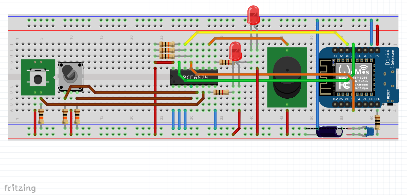
<_Arduino IDE Source code_> ` /* * PCF8574 GPIO Port Expand for ESP8266_PCF8574_with_EC11_RotaryEncoder_Led_Beeper * * PCF8574 ----- WeMos-D1 Mini/Pro (LOLIN) * A0 ----- GND * A1 ----- GND * A2 ----- GND * VSS ----- GND * VDD ----- 3.3V * SDA ----- GPIO_4 (D2) * SCL ----- GPIO_5 (D1) * INT ----- GPIO_14 (D5) (DO NOT USE D0, D3, D4 or D8 because of pull-Up !!, they will NOT WORK, or device is not possible to program, or does NOT start on PowerUp) * (ONLY USE D5, D6 or D7 !!!!) * * ----------------- LET OP is Negative logic !!! * P0 ----------------- RE_Kanaal-A (Input with Pull_Down 10k to GND, common connection to +3V3) (or 5v) * P1 ----------------- RE_Kanaal-B (Input with Pull_Down 10k to GND, common connection to +3V3) (or 5v) * P2 ----------------- RE_Switch (Input with Pull_Down 10k to GND, common connection to +3V3) (or 5v) * P3 ----------------- LED (Led1) (Output) LED via 1k to 3V3 (or 5V) * P4 ----------------- LED (Led2) (Output) LED via 1k to 3V3 (or 5V) * P5 ----------------- BEEPER (Output) Beeper to 3V3 (or 5V) * P6 ----------------- (NC)BUTTON OR OUTPUT * P7 ----------------- (NC)BUTTON OR OUTPUT * */ #include "Arduino.h" #include "PCF8574.h" // https://github.com/xreef/PCF8574_library #define ESP8266_INTERRUPTED_PIN D5 // used Interrupt Pin on ESP8266 // Set PCF8574 i2c address PCF8574 pcf8574(0x38); // Function interrupt Flag from PCF8574 bool pcfInt = false; // Output LED(s) on PCF8574 struct LED { int ledPin; // Used PinOnPCF unsigned long ledOnOffTime; // Time Led is ON and after that Time Led is OFF (2x value entered) bool ledIsON = false; // Default at Create unsigned long ledLastChanged = 0; // Default at Create } ; LED Led1; // Led #1 LED Led2; // Led #2 // Output LED(s) on PCF8574 struct BEEPER { int beepPin; // Used PinOnPCF int beepType; // NumBeeps (0 = Stop Beeping, 1..254 = NumBeeps, 255 = Continuous Beeps) unsigned long highDuration; // Time the Beeper is OFF unsigned long lowDuration; // Time the Beeper is ON bool beeperIsON = false; // Default at Create bool beepStatus = false; // Default at Create (Start/Stop Flag) int beepCountDown = 0; // Default at Create (Value starts the same as NumBeeps (beepType), counts down to 0) unsigned long beepLastChanged = 0; // Default at Create (Time of last change) } ; BEEPER Beep1; // Beeper #1 // Encoder EC11 on PCF String EncoderSeq = ""; //LeftTurn=BABA, RightTurn=AABB, SwitchPress=SW static unsigned long LastTimeSeqChanged = 0; // Use here to prohibit when Blinking of the Leds is a problem to get out of Sync !!! unsigned long currentTime; void pcfInterruptOnPCF8574(){ pcfInt = true; } void setup() { // Setup of the Led(s) Led1.ledPin = 3; Led1.ledOnOffTime = 1000; Led2.ledPin = 4; Led2.ledOnOffTime = 500; // Setup of the Beeper(s) Beep1.beepPin = 5; Serial.begin(115200); while (!Serial) { delay(500); } Serial.println(); Serial.println("Serial Port Ready"); // Instellen Interrupt for PCF8574 pinMode(ESP8266_INTERRUPTED_PIN, INPUT_PULLUP); attachInterrupt(digitalPinToInterrupt(ESP8266_INTERRUPTED_PIN), pcfInterruptOnPCF8574, FALLING); // Instellen ALL ports as Input on PCF8574 for(int i=0;i<8;i++) { pcf8574.pinMode(i, INPUT); } // Instellen used "LED" as Output on PCF8574 pcf8574.pinMode(Led1.ledPin, OUTPUT); pcf8574.pinMode(Led2.ledPin, OUTPUT); // Instellen used "BEEPER" as Output on PCF8574 pcf8574.pinMode(Beep1.beepPin, OUTPUT); pcf8574.begin(); Serial.println("Application has been started"); // Switch "LED" OFF on PCF8574 pcf8574.digitalWrite(Led1.ledPin,HIGH); pcf8574.digitalWrite(Led2.ledPin,HIGH); // Switch "Beeper" OFF on PCF8574 pcf8574.digitalWrite(Beep1.beepPin,HIGH); // Delay before Start... //delay(2000); } void LedBlink(LED &whichLed) { // Check if the LED needs to be Switched (once every ledOnOffTime msec.) if (currentTime - whichLed.ledLastChanged > whichLed.ledOnOffTime) { // Instead of Delay() if (whichLed.ledIsON) { pcf8574.digitalWrite(whichLed.ledPin,HIGH); whichLed.ledIsON = false; } else { pcf8574.digitalWrite(whichLed.ledPin,LOW); whichLed.ledIsON = true; } // Keep track of when we were here last (no more than every ledOnOffTime msec.) whichLed.ledLastChanged = currentTime; } } void Beep(BEEPER &whichBeep) { if(whichBeep.beeperIsON == true) { if (whichBeep.beepCountDown >= 0) { if ((currentTime - whichBeep.beepLastChanged) >= whichBeep.lowDuration) { whichBeep.beepLastChanged = currentTime; pcf8574.digitalWrite(whichBeep.beepPin,HIGH); whichBeep.beeperIsON = false; // For keeping track of counting beeps (1 full beep cycle finished) if ((whichBeep.beepType > 0) & (whichBeep.beepType < 255)) whichBeep.beepCountDown--; } } } else { // First loop goes allway through here !!! if ((currentTime - whichBeep.beepLastChanged) >= whichBeep.highDuration) { whichBeep.beepLastChanged = currentTime; pcf8574.digitalWrite(whichBeep.beepPin,LOW); whichBeep.beeperIsON = true; } } // Control the status of the beep loop if (whichBeep.beepCountDown > 0) { whichBeep.beepStatus = true; } else { if (whichBeep.beeperIsON == false) { whichBeep.beepStatus = false; } } } void CheckRecvPcfSeq() { unsigned long CheckTime = millis(); // Check if the Sequence needs to be handled (once every 50..100 ms, for debounce) if (CheckTime - LastTimeSeqChanged > 50) { // Instead of Delay() after last Input char is received // Handle the Sequence LeftTurn=BABA, RightTurn=AABB, SwitchPress=SW if (EncoderSeq[0] == 'B') { Serial.println("LeftTurn"); // OR DO ActionX } else if (EncoderSeq[0] == 'A') { Serial.println("RightTurn"); // OR DO ActionY } else if (EncoderSeq[0] == 'S') { Serial.println("SwitchPress"); // OR DO ActionZ doBeeps(); } // else for adding more inputs EncoderSeq = ""; LastTimeSeqChanged = 0; } } void CheckPcfInputs() { if (pcfInt){ //Serial.println("PCF Interrupt received !!"); PCF8574::DigitalInput val = pcf8574.digitalReadAll(); // Process read Encoder Inputs if (val.p0==HIGH) { // Kan-A = High EncoderSeq += "A"; } if (val.p1==HIGH) { // Kan-B = High EncoderSeq += "B"; } if (val.p2==HIGH) { // Switch is Pressed EncoderSeq += "SW"; } // // Display Encoder Inputs // Serial.print(val.p0); // Serial.print(" - "); // Serial.print(val.p1); // Serial.print(" - "); // Serial.println(val.p2); // // Serial.println(EncoderSeq); // if (val.p3==HIGH) Serial.println("KEY3 PRESSED"); // In use as an Output LED #1 // if (val.p4==HIGH) Serial.println("KEY4 PRESSED"); // In use as an Output LED #2 // if (val.p5==HIGH) Serial.println("KEY5 PRESSED"); // In use as an Output BEEPER #1 // // Still FREE to USE // if (val.p6==HIGH) Serial.println("KEY6 PRESSED"); // NOT USED YET // if (val.p7==HIGH) Serial.println("KEY7 PRESSED"); // NOT USED YET // Timer for processing every 50..100 msec. LastTimeSeqChanged = millis(); pcfInt = false; } } void doBeeps() { // Check (and SOUND) the BEEPER if (Beep1.beepStatus == false) { //Serial.println("Prepare new Start of the Beeper Loop"); // Setup of the Beeper(s) Beep1.beepPin = 5; // Pin used Beep1.beepType = 4; // 0 = Stop Beeping, 1..254 = NumBeeps, 255 = Continuous Beeps Beep1.beepCountDown = 4; // Starts the same as Num Beeps, counts down to 0 (if > 0 and < 255) Beep1.highDuration = 75; // Time the Beeper is OFF Beep1.lowDuration = 75; // Time the Beeper is ON Beep1.beepLastChanged = 0; // Time of last change Beep1.beepStatus = true; // Start running the above Set functionality of Beeps } } void loop() { // use here to prohibit when Blinking of the Leds is a problem to get out of Sync !!! currentTime = millis(); // Check (and CHANGE) the LED LedBlink(Led1); LedBlink(Led2); // Only do Beep1 if told to run (in doBeeps(), for now triggered by pressing the EncoderSwitch) if (Beep1.beepStatus == true) Beep(Beep1); // Check the PCF Inputs CheckPcfInputs(); CheckRecvPcfSeq(); } ` ![Fritzing Project](https://user-images.githubusercontent.com/29839805/65508103-c1a62b00-decf-11e9-9a72-ef22d1fd0b1f.png)
xreef commented 4 years ago

Hi, can you try to use the integrated procedure for interrupt? In the example readAll_Interrupt.ino you can find an integrated solution for interrupt, It's not so relevant difference but try this

PCF8574 pcf8574(0x39, ESP8266_INTERRUPTED_PIN, pcfInterruptOnPCF8574);

And for a better debug remove comment from this line on PCF8574.h

// Uncomment to enable printing out nice debug messages. // #define PCF8574_DEBUG

Tell me about the result. Bye

MAWMN commented 4 years ago

Hi, The example program was working aswell as the Debug information. The extra line did not change anything:

PCF8574 pcf8574(0x39, ESP8266_INTERRUPTED_PIN, pcfInterruptOnPCF8574)

I think it is more a hardware than a software thing...

Also did some furter tests of my application, see the results below of my findings.

The Wemos device has 11 IO's Pins D1, D2, are used for I2C as SDA and SCL Pins D5, D6, D7 and D8 are used for SPI Pins Tx, Rx, I tried to use the pins Rx (GPIO3) and TX (GPIO1) in function mode 3 but this did not work. https://www.youtube.com/watch?v=D9mBQ_WL7tE

So now the only Pins available for Interrupt are : D0 - GPIO16 - This Pin has NO interrupt/pwm/I2C/one-wire support (So NOT usable for Interrupt)

D4 - GPIO2 - The interrupt is working, however :

D3 - GPIO0 - The interrupt is working, however :

MAWMN commented 4 years ago

Hi, finally made some progress..after a lot of playing arround, testing and googling for possible solutions. The first thing I did was making it possible to use other pins for SDA and SCL so the default once came available for my Interrupt.. This worked OKE, but unfortunately my libraries for my OLED display and IN219 did not like this and would not work with this alternative configuration. After a lot of googling I finaly changed my ESP configuration from 2.5.0 to 2.5.2 (latest) and directly got lots of reboots. Here it seemed the ISR routine needed an addition which I found after again some googling.. I was able to compile and upload now, and everything worked like a charme with the default SDA and SCL Pins, the INT pin on D3, and NO more problems in uploading and after a powerUp or Reset as I had before...

Seems everything was solved, yeah...

Once more my now working code for anyone who is also facing these kind of problems..

`< /* * PCF8574 GPIO Port Expand for ESP8266_PCF8574_with_EC11_RotaryEncoder_Led_Beeper * * CONDITION !! : USE ESP version 2.5.2 <=== * * PCF8574 ----- WeMos-D1 Mini/Pro (LOLIN) * A0 ----- GND * A1 ----- GND * A2 ----- GND * VSS ----- GND * VDD ----- 3.3V * SDA ----- GPIO_4 (D2) No External pull-Up used * SCL ----- GPIO_5 (D1) No External pull-Up used * INT ----- GPIO_0 (D3) No External pull-Up used (Already 12k inside) * DONT USE D0, Pin has NO Interrupt / Pwm / I2C/ One-Wire Support * * ----------------- WATCH OUT.. PCF8574 Chip is using Negative logic !!! * P0 ----------------- RE_Kanaal-A (Input with Pull_Down 10k to GND, common connection to +3V3) (or 5v) * P1 ----------------- RE_Kanaal-B (Input with Pull_Down 10k to GND, common connection to +3V3) (or 5v) * P2 ----------------- RE_Switch (Input with Pull_Down 10k to GND, common connection to +3V3) (or 5v) * P3 ----------------- LED (Led1) (Output) LED via 1k to 3V3 (or 5V) * P4 ----------------- LED (Led2) (Output) LED via 1k to 3V3 (or 5V) * P5 ----------------- BEEPER (Output) Beeper to 3V3 (or 5V) * P6 ----------------- (NC)BUTTON OR OUTPUT * P7 ----------------- (NC)BUTTON OR OUTPUT * */ #include "Arduino.h" #include "PCF8574.h" // https://github.com/xreef/PCF8574_library //#include "wire.h" // DONT USE, Is only for alternative SDA and SCL necessary #define PCF_ADDR 0x38 //#define ESP8266_SDA D3 // DONT USE, This Alternative creates problem with other I2C Libraries //#define ESP8266_SCL D4 // DONT USE, This Alternative creates problem with other I2C Libraries #define ESP8266_SDA D2 // Used SDA Pin on ESP8266 (Default) #define ESP8266_SCL D1 // Used SCL Pin on ESP8266 (Default) #define ESP8266_INTERRUPTED_PIN D3 // Used Interrupt Pin on ESP8266 // Set PCF8574 i2c address //PCF8574 pcf8574(PCF_ADDR, ESP8266_SDA, ESP8266_SCL); // DONT USE, Is only for alternative SDA and SCL necessary PCF8574 pcf8574(PCF_ADDR); // Function Interrupt Flag from PCF8574 bool pcfInt = false; // Output LED(s) on PCF8574 struct LED { int ledPin; // Used PinOnPCF unsigned long ledOnOffTime; // Time Led is ON and after that Time Led is OFF (TotalTime is 2x value entered) bool ledIsON = false; // Default at Create unsigned long ledLastChanged = 0; // Default at Create } ; LED Led1; // Led #1 LED Led2; // Led #2 // Output LED(s) on PCF8574 struct BEEPER { int beepPin; // Used PinOnPCF int beepType; // NumBeeps (0 = Stop Beeping, 1..254 = NumBeeps, 255 = Continuous Beeps) unsigned long highDuration; // Time the Beeper is OFF unsigned long lowDuration; // Time the Beeper is ON bool beeperIsON = false; // Default at Create bool beepStatus = false; // Default at Create (Start/Stop Flag) int beepCountDown = 0; // Default at Create (Value starts the same as NumBeeps (beepType), counts down to 0) unsigned long beepLastChanged = 0; // Default at Create (Time of last change) } ; BEEPER Beep1; // Beeper #1 // Encoder EC11 on PCF String EncoderSeq = ""; //LeftTurn=BABA, RightTurn=AABB, SwitchPress=SW static unsigned long LastTimeSeqChanged = 0; // Use here to prohibit when Blinking of the Leds is a problem to get out of Sync !!! unsigned long currentTime; //void pcfInterruptOnPCF8574(){ // Interrupt function <= V2.5.0 !!! ICACHE_RAM_ATTR void pcfInterruptOnPCF8574(){ // Interrupt function >= V2.5.2 !!! pcfInt = true; } void setup() { // Replace the Wire.begin() //Wire.begin(ESP8266_SCL, ESP8266_SDA); // DONT USE, Is only for alternative SDA and SCL necessary // Params for the Led(s) Led1.ledPin = 3; Led1.ledOnOffTime = 1000; Led2.ledPin = 4; Led2.ledOnOffTime = 500; // Params for the Beeper(s) Beep1.beepPin = 5; Serial.begin(115200); Serial.println(); Serial.println("Serial Port Ready"); // Setup the Interrupt for PCF8574 pinMode(ESP8266_INTERRUPTED_PIN, INPUT_PULLUP); attachInterrupt(digitalPinToInterrupt(ESP8266_INTERRUPTED_PIN), pcfInterruptOnPCF8574, FALLING); // Setup the ALL ports as Input on PCF8574 for(int i=0;i<8;i++) { pcf8574.pinMode(i, INPUT); } // Setup the used "LED" as Output on PCF8574 pcf8574.pinMode(Led1.ledPin, OUTPUT); pcf8574.pinMode(Led2.ledPin, OUTPUT); // Setup the used "BEEPER" as Output on PCF8574 pcf8574.pinMode(Beep1.beepPin, OUTPUT); // Initialize the PCF8574 pcf8574.begin(); Serial.println("Application has been started"); // Switch the "LED" OFF on PCF8574 pcf8574.digitalWrite(Led1.ledPin,HIGH); pcf8574.digitalWrite(Led2.ledPin,HIGH); // Switch the "Beeper" OFF on PCF8574 pcf8574.digitalWrite(Beep1.beepPin,HIGH); // Delay before Start... //delay(2000); } void LedBlink(LED &whichLed) { // Check if the LED needs to be Switched (once every ledOnOffTime msec.) if (currentTime - whichLed.ledLastChanged > whichLed.ledOnOffTime) { // Instead of Delay() if (whichLed.ledIsON) { pcf8574.digitalWrite(whichLed.ledPin,HIGH); whichLed.ledIsON = false; } else { pcf8574.digitalWrite(whichLed.ledPin,LOW); whichLed.ledIsON = true; } // Keep track of when we were here last (no more than every ledOnOffTime msec.) whichLed.ledLastChanged = currentTime; } } void Beep(BEEPER &whichBeep) { if(whichBeep.beeperIsON == true) { if (whichBeep.beepCountDown >= 0) { if ((currentTime - whichBeep.beepLastChanged) >= whichBeep.lowDuration) { // Instead of Delay() whichBeep.beepLastChanged = currentTime; pcf8574.digitalWrite(whichBeep.beepPin,HIGH); whichBeep.beeperIsON = false; // For keeping track of counting beeps (1 full beep cycle finished) if ((whichBeep.beepType > 0) & (whichBeep.beepType < 255)) whichBeep.beepCountDown--; } } } else { // First loop goes allway through here !!! if ((currentTime - whichBeep.beepLastChanged) >= whichBeep.highDuration) { // Instead of Delay() whichBeep.beepLastChanged = currentTime; pcf8574.digitalWrite(whichBeep.beepPin,LOW); whichBeep.beeperIsON = true; } } // Control the status of the beep loop if (whichBeep.beepCountDown > 0) { whichBeep.beepStatus = true; } else { if (whichBeep.beeperIsON == false) { whichBeep.beepStatus = false; } } } void CheckRecvPcfSeq() { unsigned long CheckTime = millis(); // Check if the Sequence needs to be handled (once every 50 ms, for debounce) if (CheckTime - LastTimeSeqChanged > 50) { // Instead of Delay() after last Input char is received // Handle the Sequence LeftTurn=BABA, RightTurn=AABB, SwitchPress=SW if (EncoderSeq[0] == 'B') { Serial.println("LeftTurn"); // OR DO ActionX } else if (EncoderSeq[0] == 'A') { Serial.println("RightTurn"); // OR DO ActionY } else if (EncoderSeq[0] == 'S') { Serial.println("SwitchPress"); // OR DO ActionZ doBeeps(); } // else for adding more inputs EncoderSeq = ""; LastTimeSeqChanged = 0; } } void CheckPcfInputs() { if (pcfInt){ //Serial.println("PCF Interrupt received !!"); // Create the Encoder Input Sequence PCF8574::DigitalInput val = pcf8574.digitalReadAll(); // Process read Encoder Inputs if (val.p0==HIGH) { // Kan-A = High EncoderSeq += "A"; } if (val.p1==HIGH) { // Kan-B = High EncoderSeq += "B"; } if (val.p2==HIGH) { // Switch is Pressed EncoderSeq += "SW"; } // // Display Encoder Inputs // Serial.print(val.p0); // Serial.print(" - "); // Serial.print(val.p1); // Serial.print(" - "); // Serial.println(val.p2); // // Serial.println(EncoderSeq); // if (val.p3==HIGH) Serial.println("KEY3 PRESSED"); // In use as an Output LED #1 // if (val.p4==HIGH) Serial.println("KEY4 PRESSED"); // In use as an Output LED #2 // if (val.p5==HIGH) Serial.println("KEY5 PRESSED"); // In use as an Output BEEPER #1 // // Still FREE to USE // if (val.p6==HIGH) Serial.println("KEY6 PRESSED"); // NOT USED YET // if (val.p7==HIGH) Serial.println("KEY7 PRESSED"); // NOT USED YET // (Re)Set Timer for processing every 50 msec. LastTimeSeqChanged = millis(); pcfInt = false; } } void doBeeps() { // Check (and SOUND) the BEEPER if (Beep1.beepStatus == false) { //Serial.println("Prepare new Start of the Beeper Loop"); // Setup of the Beeper(s) Beep1.beepPin = 5; // Pin used Beep1.beepType = 4; // 0 = Stop Beeping, 1..254 = NumBeeps, 255 = Continuous Beeps Beep1.beepCountDown = 4; // Starts the same as Num Beeps, counts down to 0 (if > 0 and < 255) Beep1.highDuration = 75; // Time the Beeper is OFF Beep1.lowDuration = 75; // Time the Beeper is ON Beep1.beepLastChanged = 0; // Time of last change Beep1.beepStatus = true; // Start running the above Set functionality of Beeps } } void loop() { // Update the currenTime currentTime = millis(); // Check (and CHANGE) the LED LedBlink(Led1); LedBlink(Led2); // Only do Beep1 if told to run (in doBeeps(), for now triggered by pressing the Encoder Switch) if (Beep1.beepStatus == true) Beep(Beep1); // Check the PCF Inputs CheckPcfInputs(); CheckRecvPcfSeq(); } >`
xreef commented 4 years ago

I'm glad that all work. Thanks for share your code and your solution. Bye