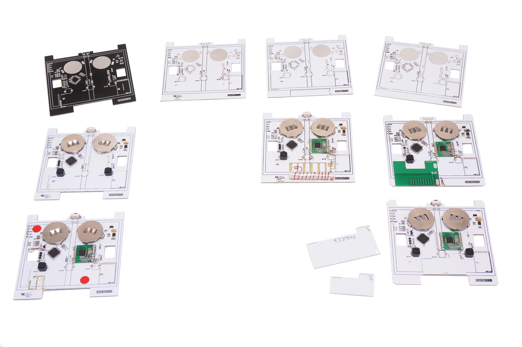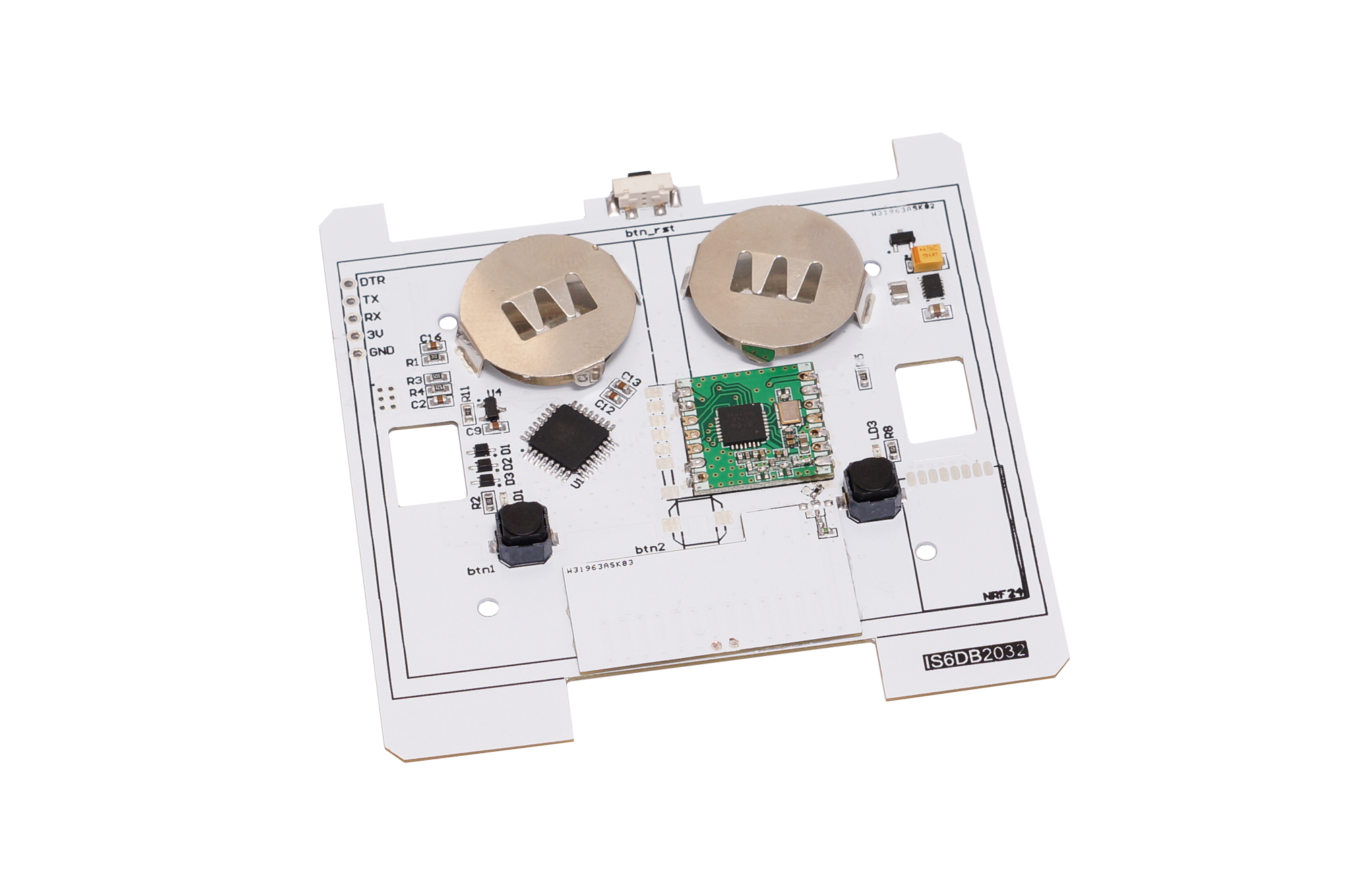
The Switch Box is a low cost wireless Arduino IDE compatible (the Atmel ATMega328P) microcontroller with HopeRF LoRa RFM95 / 69 433/868/915 radio on-board. Best sutable for Home Automation, IOT. Could be used as switch board for radio controlling any DIY project. You may think of it as Arduino Pro Mini plus all the items in the picture below:

Features & Specifications
IDE Control:
- Fully compatible with the Arduino IDE
- Enumerates as an Arduino Pro Mini @ 8 MHz
- Compatible with all RFM 69 \ 95 compatible open source libraries available
Radio Transceivers:
Three transceiver options are available
- HopeRF RFM95 LoRa® 433/868/915 MHz (long-range version)
- HopeRF RFM69-HCW 433/868/915 MHz (mid-range version)
- HopeRF RFM69-CW 433/868/915 MHz (low power consumption version)
- Footprint available for replacing RFM radios with NRF24L01+ 2.4 GHz radio
Security:
- On-board Atmel/Microchip ATSHA204A crypto-authentication chip provides secured handshakes
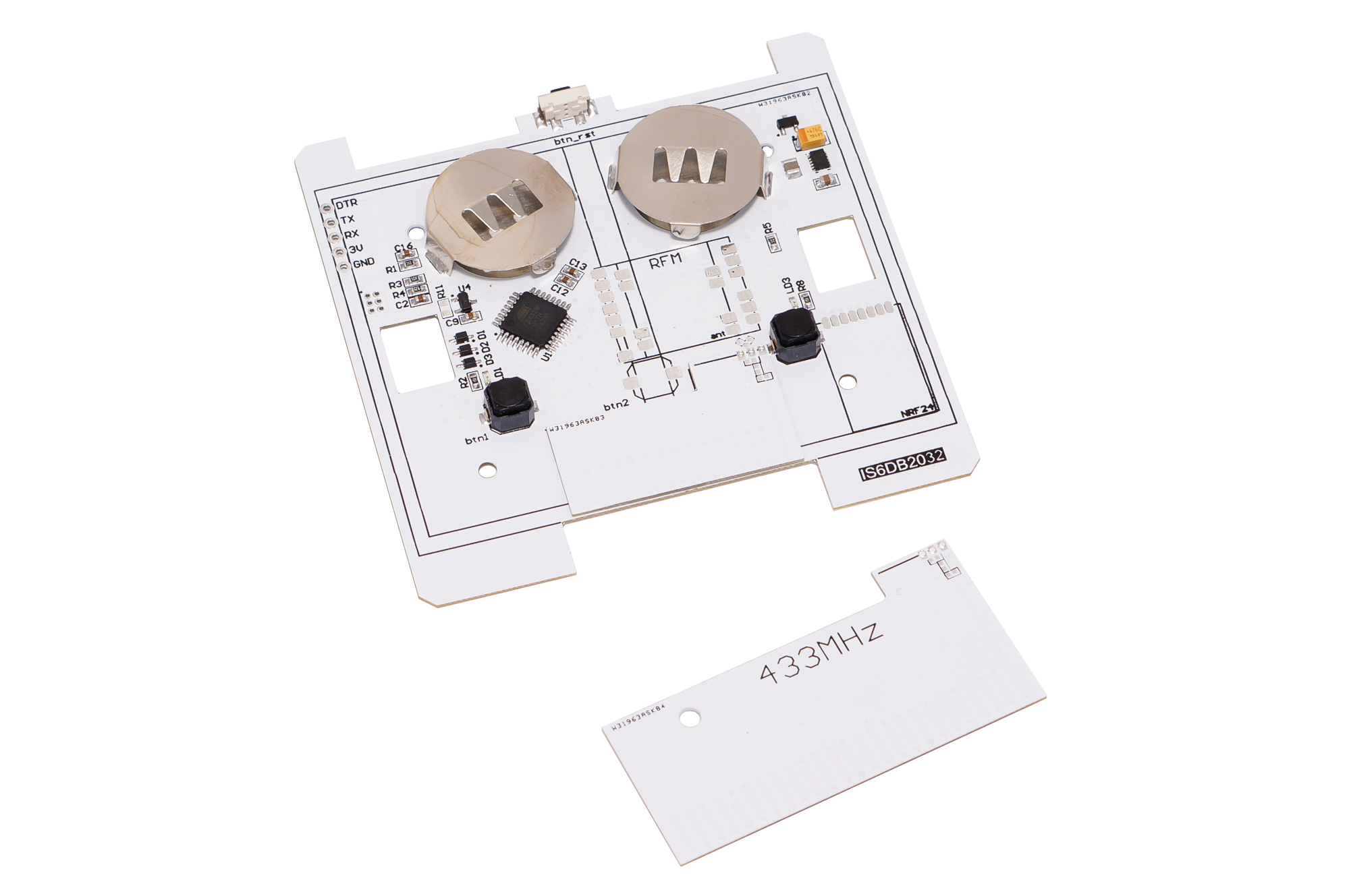
Antennas:
Tuned PCB antenna options that are soldered to the main board
- 915 MHz - United States, Canada, Australia
- 868 MHz - Europe
- 433 MHz - Europe
Interface:
- Long-run soft-touch buttons similar to high-quality home switches
- Each button has a built-in LED for message delivery confirmation
- Reset switch
Power:
Utilizes two CR2032 coin cell batteries
- On-board coin cell holders
- Reverse polarity protection
- High-efficiency power converter
- Batteries can last as long as two years with daily use
- Battery voltage sensor (via divider)
- Sleep current consumption 5uA
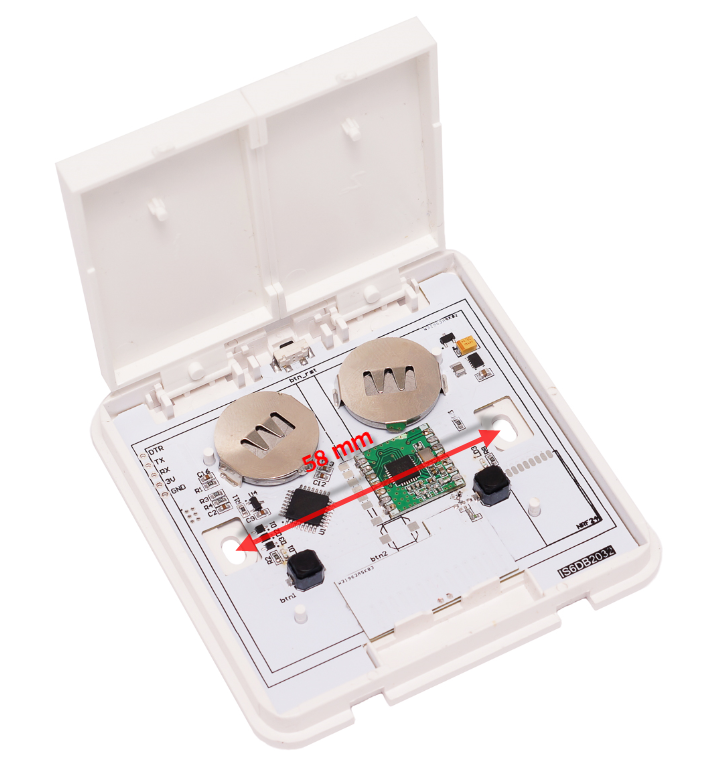
Mounting:
Two options are provided for mounting
- Adhesive tape on the back
- Screws through holes in the back plate
- Dimensions 86*86*16 mm
If you find the switch box useful, it is possible to buy it here: link to buy
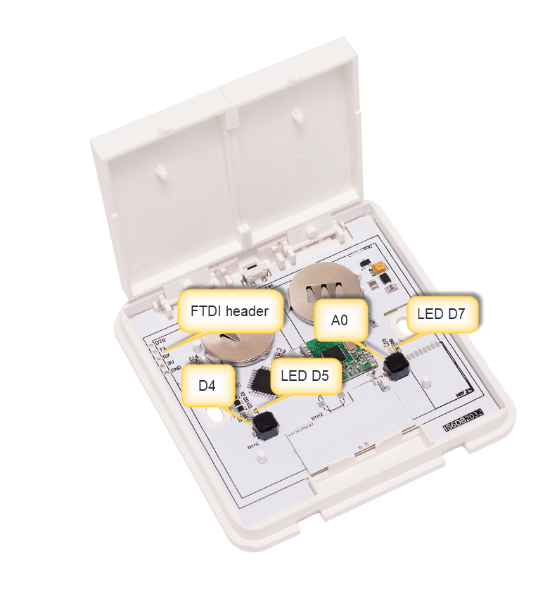
Pin out:
| Arduino Pins | Description |
|---|---|
| A6 | Connected to Battery voltage sensor (via divider) |
| A3 | Connected to ATSHA204A |
| D4, D8, A0 | Connected to momentary switch buttons |
| Interrupt 1 | Occurs when either button is pressed |
| D5, D6, D7 | Connected to LED's |
Arduino IDE Settings
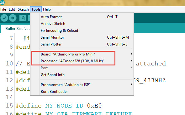
programming FTDI adapter connection
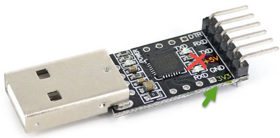
3.3V power option should be used.
the Arduino example sketches
Easy sensors API sketches. Can use both LoRa RFM95 and RFM69 radios EasySwitchBoxMySensors.ino - the switchBox Sketch GatewaySerialMySensors.ino - the receiver serial Gateway Sketch
Moteino API sketches. RFM69 radio used Moteino.ino - the switchBox Sketch MoteinoGW.ino the receiver Sketch
RadioHead API sketches. LoRaRFM95 radio used
rf95_reliable_datagram_server.ino the receiver Sketch
RHswitchBox.ino - the switchBox Sketch
Design files link. https://circuitmaker.com/Projects/Details/Yury-Sviryda/EasySwitchBox
How to use it as home automation (IOT) node controller
EasySwitchBoxMySensors.ino is the Arduino example sketch using MySensors API.
Burn the sketch into and the switchBox will became one of the MySensors home automation network Node. To create the network you need controller and at least two Nodes one as a Sensor, relay or switch Node and the other one as “Gateway Serial”. I personally love Domoticz as conroller. Please check this HowTo to install Domoticz.
Done
The board is created by Koresh
Prototype history