Commander X16 update program
This program allows you to upgrade (or downgrade) the firmware of your CX16 internal and external components in a very user friendly way and with minimal preparations and/or manual actions during the update process:
| Component | Location | Purpose | File(s) | Size |
|---|---|---|---|---|
| VERA | internal CX16 board | This FPGA made by Frank Van den Hoef, handles the CX16 - graphics and the SD card operations | VERA.BIN |
128KB |
| VERA | external VERA cardridge | This cardridge allows to connect an extra monitor to your CX16, and has a separate graphics engine! | VERA1.BIN |
128KB |
| SMC | internal CX16 board | This microcontroller handles your mouse, keyboard and timer. It is essential to boot your CX16. | SMC.BIN |
2KB |
| ROM | internal CX16 board | The main CX16 ROM contains the DOS and KERNAL to run your CX16. | ROM.BIN |
512KB |
| ROM | external CX16 cardridge | This cardridge allows you to extend the memory of your CX16 with (7) extra ROM or RAM ICs, fitted into a PCI slot on your CX16 board. | ROMn.BIN |
7x512KB |
[!IMPORTANT] There are manual actions or preparations needed to update your CX16 components! So don't just run this program but first carefully read this User Manual!
Table of contents:
1 User Manual 2 Run the CX16 update program 3 Issues and Resolutions 4 Recovery from a bricked CX16
Notice of caution
Updating your on-board firmware requires you to carefully follow the instructions. There is a small risk that your on-board firmware may get damaged during the update process and may generate your CX16 unusable, resulting in a bricked CX16!
Further steps to mitigate and recover from such situations is always possible. However, these actions are pending to be documented. Please direct youself in such situations to the Commander X16 Discord or Forum!
1 User Manual
Please consider this user manual as a first guide how to use the update program. This user manual is compatible with the CX16 update program version 3.0.0.
[!NOTE]
Included are illustrative pictures that provides you a very good understanding of the overall flow. You can click on an illustration to get a zoomed view of it.
1.0 What you need
Depending on your configuration and the new released artefacts available from the CX16 community site,
specific hardware on your CX16 board will be updated. But in essence, the update should be fairly straightforward and user friendly!
- Ensure you have a valid and working SD card that has sufficient free space and is formatted in FAT32.
- You need a Commander X16 computer (the real thing).
- You optionally can have an add-on cartridge board, that is plugged in any of the 4 expansion slots. This RAM/ROM board can contain an extra 3.5 MB of RAM/ROM!
- Ensure that you have in total 6 standard computer jumper caps available:
- 1 x jumper cap for the J1 jumper pins on the CX16 main board.
- 2 x jumper caps for the J5 jumper pins on the CX16 main board.
- 1 x jumper cap for the JP1 jumper pins on the VERA board.
- 2 x jumper caps for the J1 and J2 jumper pins on the external ROM cardridge board.
That's it!
1.1 Download the program
The latest version of the program can be found on the release page of this repository. Please read through the release notes for any specific actions!
- Search for the file CX16-UPDATE.PRG and download the file.
- Copy the program into a directory of your SD card.
- You will run this program on your CX16.
- Ensure the file is copied onto the SD card with the file name in CAPITAL letters.
1.2 Download the Commander X16 community firmware release files from the web site.
Download the latest VERA.BIN, SMC.BIN and ROM.BIN file(s) from the Commander X16 community web sites.
Any additional external ROMs on the expansion card to be updated, create the ROMn.BIN files to be according your external ROM update strategy.
If you own an external VERA, download or create an extra VERA1.BIN file and copy it onto your SD card.
- SMC.BIN from the CX16 update program release page
- VERA.BIN from the VERA Release page
- ROM.BIN files from the ROM Release page.
Notes:
- The SMC Release page is not yet containing the correct SMC.BIN files, so download from the CX16 update program release page. Therefore, the CX16 update program release page contains the SMC.BIN artefacts.
- The names of the artefacts can differ a bit. They might contain the release number of version number. Always rename the files to the correct name before copying it onto the SD card!
1.3 The update PREPARATIONS:
1.3.1 Copy the files on the SD card.
Copy the SMC.BIN, VERA.BIN, VERA1.BIN, ROM.BIN and ROMn.BIN files on the SD card at the same folder fro where your CX16-UPDATE.PRG file is located according your update strategy and needs.
Ensure the files are copied onto the SD card with the file names in CAPITAL letters.
For an overview, please find the following checklists with all the actions and attention points, which are explained further below with pictures and further details.
1.3.1 PREPARE: OPEN VERA JP1 jumper pins + Be prepared for a manual action!
The VERA hosts both the SD card as the graphics FPGA engine. On the VERA main CX16 board, there are the JP1 jumper pins, which regulate whether any request to the VERA directs the request to the SD card or to the SPI. The SPI is a 2MB IC that is located on your VERA board, which is used to "flash" the FPGA at VERA startup. The CX16 ROM activates this process automatically, but in order to update the VERA firmware, the contents of this SPI IC must be updated. This requires you to place during the execution of the update program a jumper cap onto the JP1 jumper on the VERA board. This instructs the VERA to direct any memory instruction to the SPI instead of the SD card. Thus, once the SP1 jumper cap closes the JP1 jumper pins, the SPI update process will commence. Once the SPI update process is finished, you will be request to remove again the JP1 jumper cap from the VERA board, because the update program must be able to read all your further SMC.BIN, ROM.BIN, ROM1.BIN and VERA1.BIN files from the SD card.
So in summary, remember the following:
- JP1 jumper pins OPEN => VERA addresses the SD card.
- JP1 jumper pins CLOSED => VERA addresses the SPI IC.
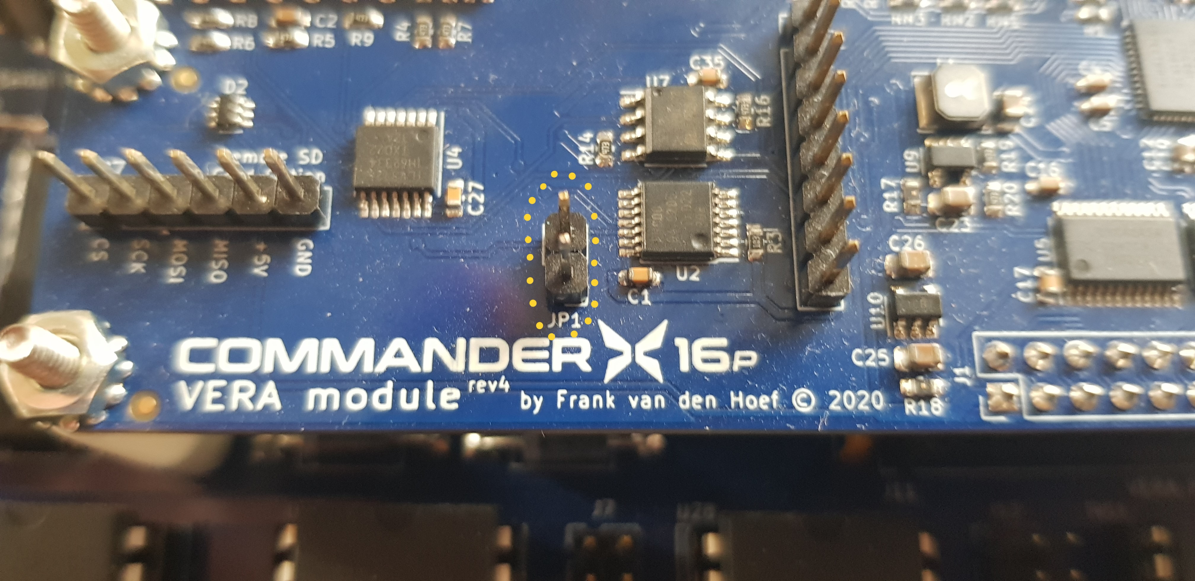 For preparation, before running the CX16 update program, ensure that the JP1 jumper pins on the VERA board are OPEN (Picture above)! This is necessary to instruct VERA to address any memory instruction to the SD card. For preparation, before running the CX16 update program, ensure that the JP1 jumper pins on the VERA board are OPEN (Picture above)! This is necessary to instruct VERA to address any memory instruction to the SD card. |
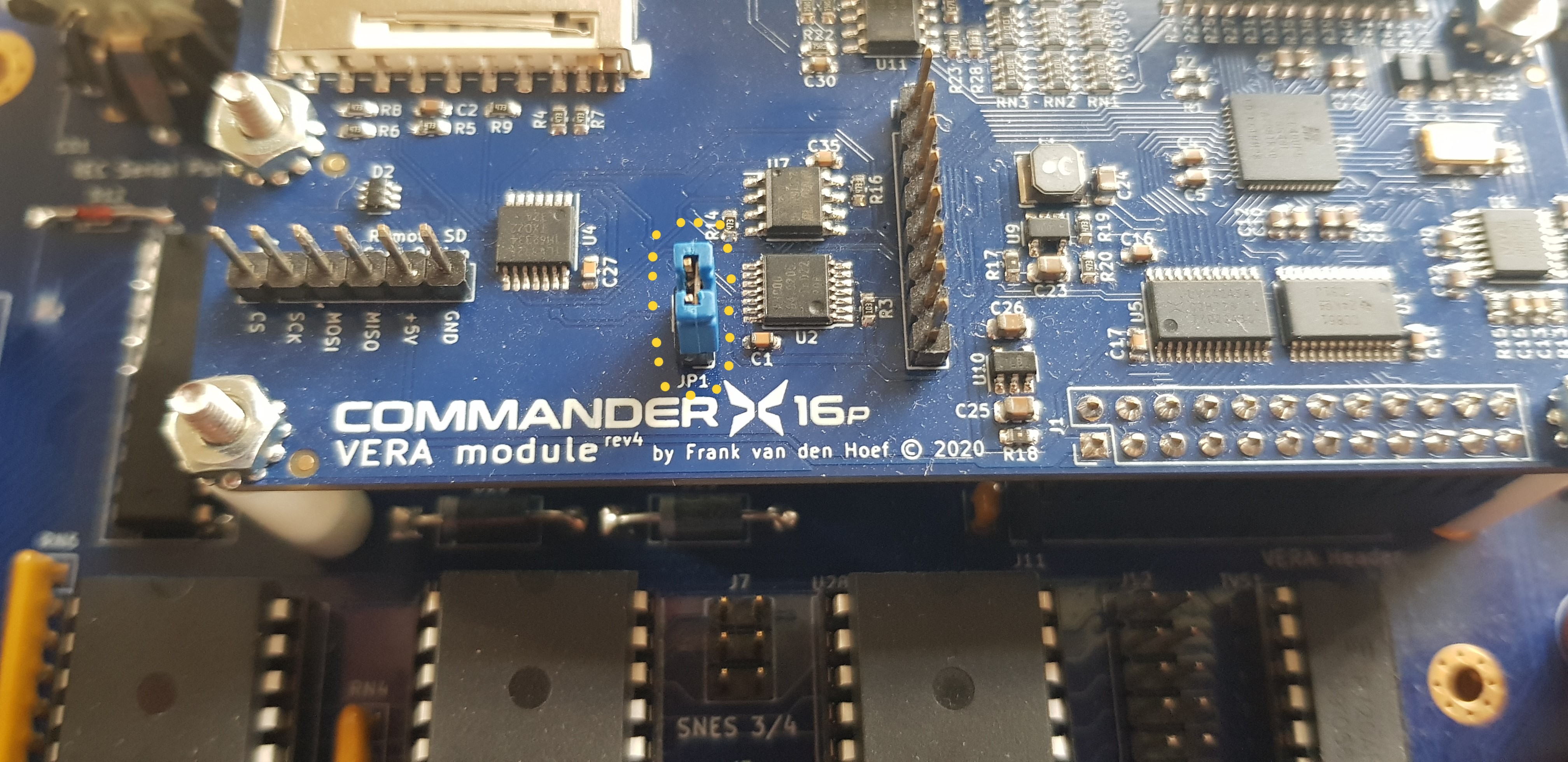 During the update process, the program will ask you to place a jumper cap, CLOSING the JP1 jumper pins (picture above). This is necessary to instruct VERA to address any memory instruction to the SPI IC, in order to allow for the memory flashing of the VERA.BIN file now stored in RAM, onto the SPI IC memory (only the first 128KB will be updated). During the update process, the program will ask you to place a jumper cap, CLOSING the JP1 jumper pins (picture above). This is necessary to instruct VERA to address any memory instruction to the SPI IC, in order to allow for the memory flashing of the VERA.BIN file now stored in RAM, onto the SPI IC memory (only the first 128KB will be updated). |
| Once the VERA memory has been updated, the program will ask you to remove the JP1 jumper cap, opening the pins again. This is necessary to direct VERA to address the SD card again for further file reads. |
[!WARNING] This will happen during the update process and it is crucial that you follow carefully the instructions given by the program! It might be advisory to practice this process before you execute the CX16 update program, with your CX16 board powered OFF! Put a jumper cap on the JP1 jumper pins closing it and re-opening it by removing. Simple, but if you've never done this, this may require a bit of practice!
[!NOTE] Updating the external VERA card won't require you to follow this process.
1.3.2 Prepare: CLOSE SMC J5 jumper pins!
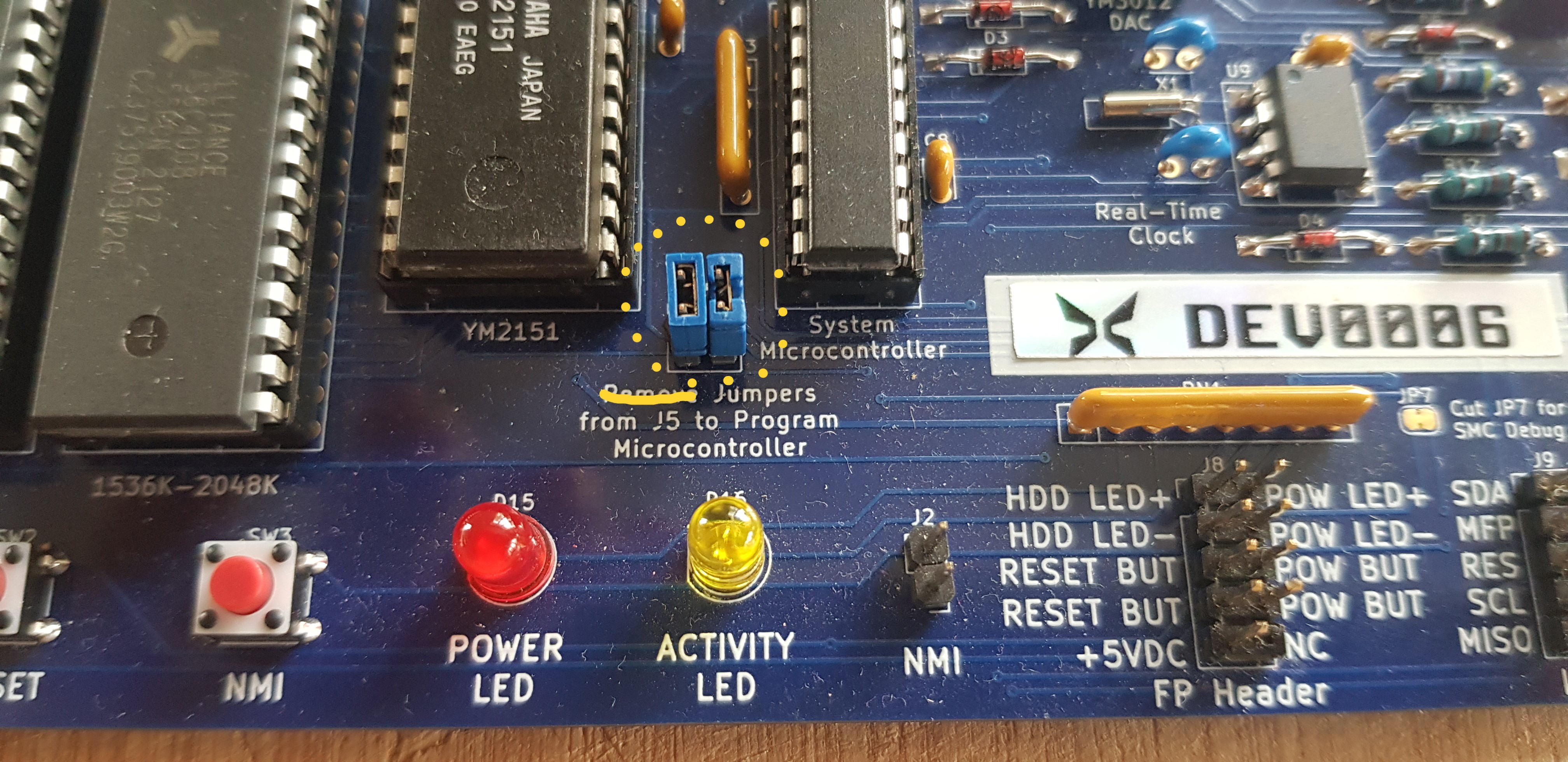 Ensure that the J5 jumper pins on the Commander X16 main board are closed. If the J5 jumper pins are not closed, the keyboard won't be functional! Ensure that the J5 jumper pins on the Commander X16 main board are closed. If the J5 jumper pins are not closed, the keyboard won't be functional! |
1.3.3 Prepare: CLOSE Main CX16 ROM J1 jumper pins!
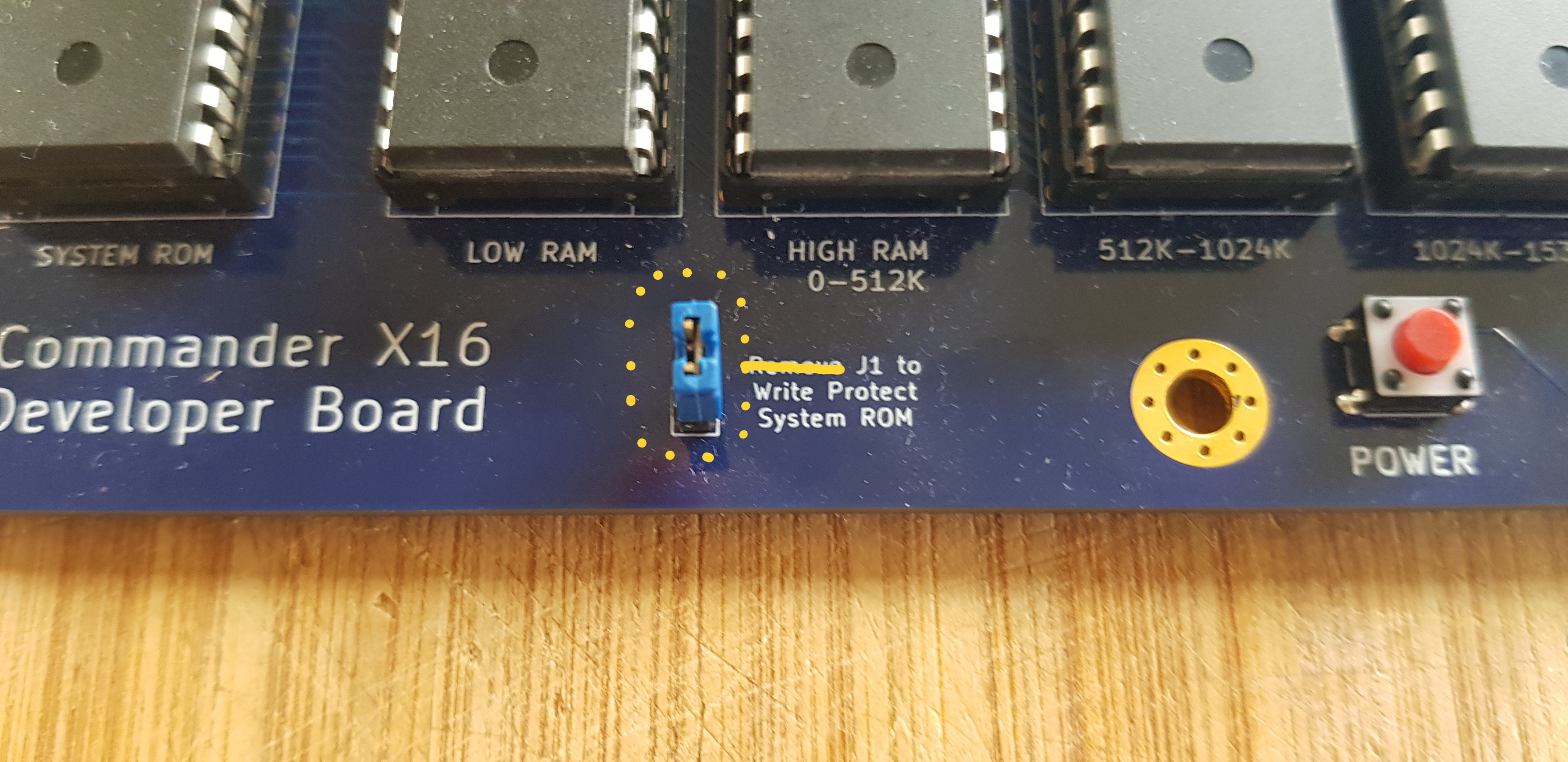 Ensure that the J1 jumper pins on the Commander X16 main board are closed, to remove the write protection of the main CX16 ROM. If the J1 jumper pins are not closed, the main CX16 ROM will not be detected by the update program! Ensure that the J1 jumper pins on the Commander X16 main board are closed, to remove the write protection of the main CX16 ROM. If the J1 jumper pins are not closed, the main CX16 ROM will not be detected by the update program! |
1.3.4 Prepare: Flash multiple ROMs on the external RAM/ROM board or cartridge.
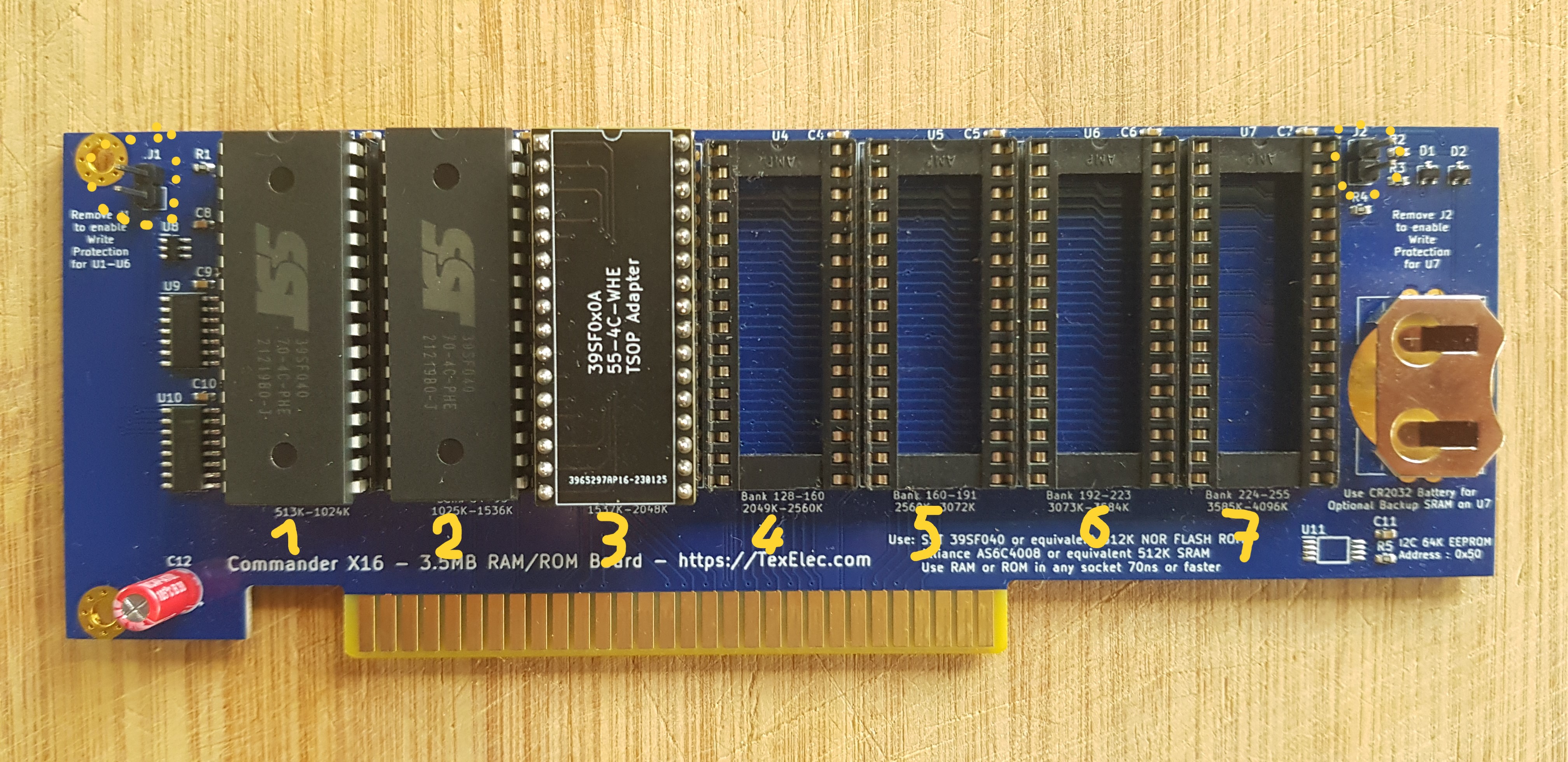 First for all clarity, find below a picture of such a ROM expansion cartridge. First for all clarity, find below a picture of such a ROM expansion cartridge. |
On the ROM cartridge, 7 extra RAM/ROM chips can be placed for usage, and can be updated using this program. The cartridge is placed in one of the 4 PCI extension slots on the CX16 main board, and provides an extra 3.5 MB of banked RAM/ROM to your CX16 between addresses $C000 and $FFFF, with zeropage $01 as the bank register. Each bank has $4000 bytes!
[!NOTE] Each ROM is addressing wise 512K separated from each other, and can be flashed with its own
ROMn.BINfile(s), where n must be a number between 1 and 7! For example,ROM1.BINwill flash ROM#1 on the cartridge.ROM5.BINwill flash ROM#5. ROMs are to be counted from left to right!
In order to flash the ROMs, close the relevant jumper pins:
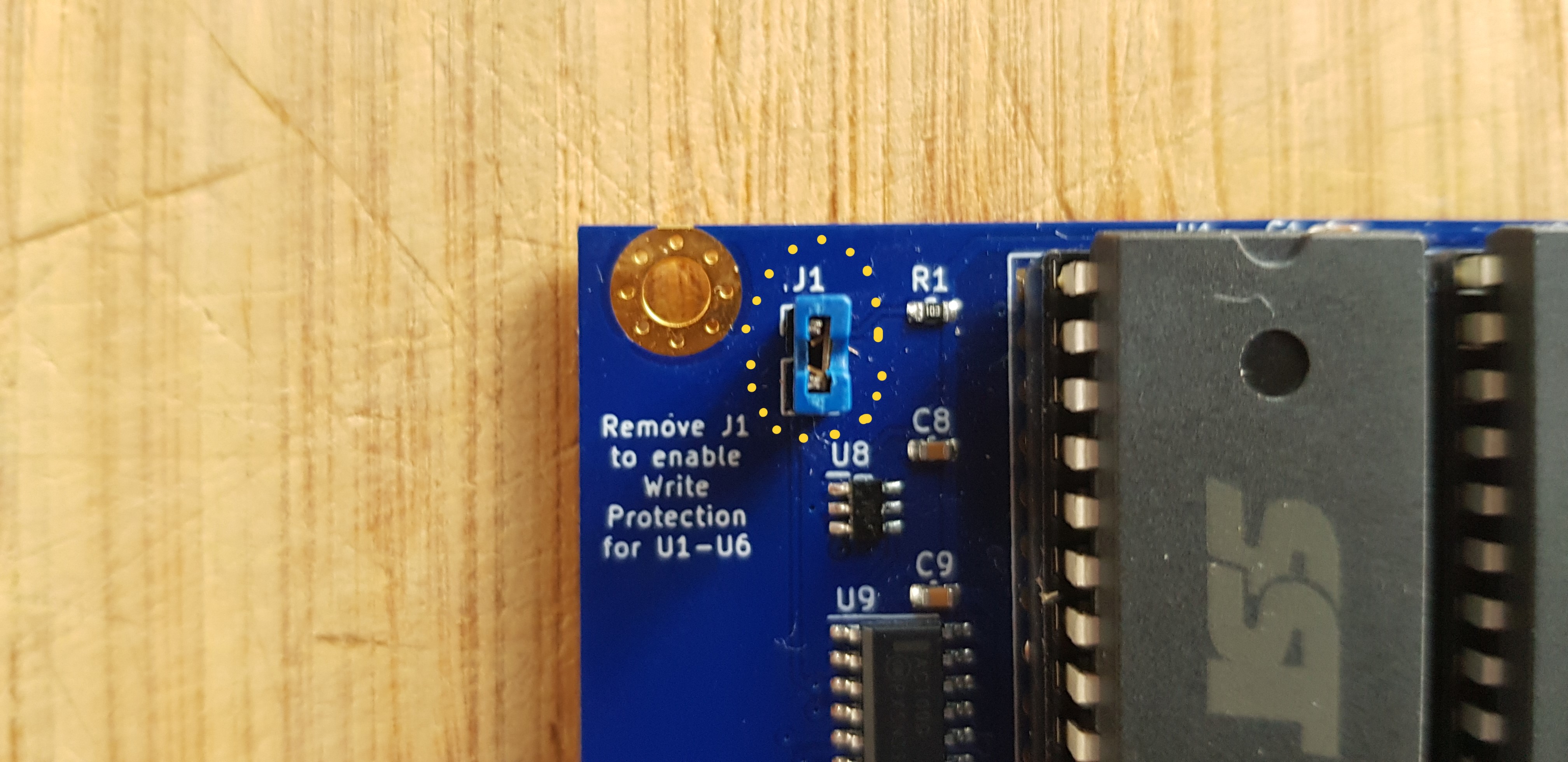 Close the J1 jumper pins (at the left side of the cartridge board) to remove the write-protection for ROM#1 till ROM#6. Close the J1 jumper pins (at the left side of the cartridge board) to remove the write-protection for ROM#1 till ROM#6. |
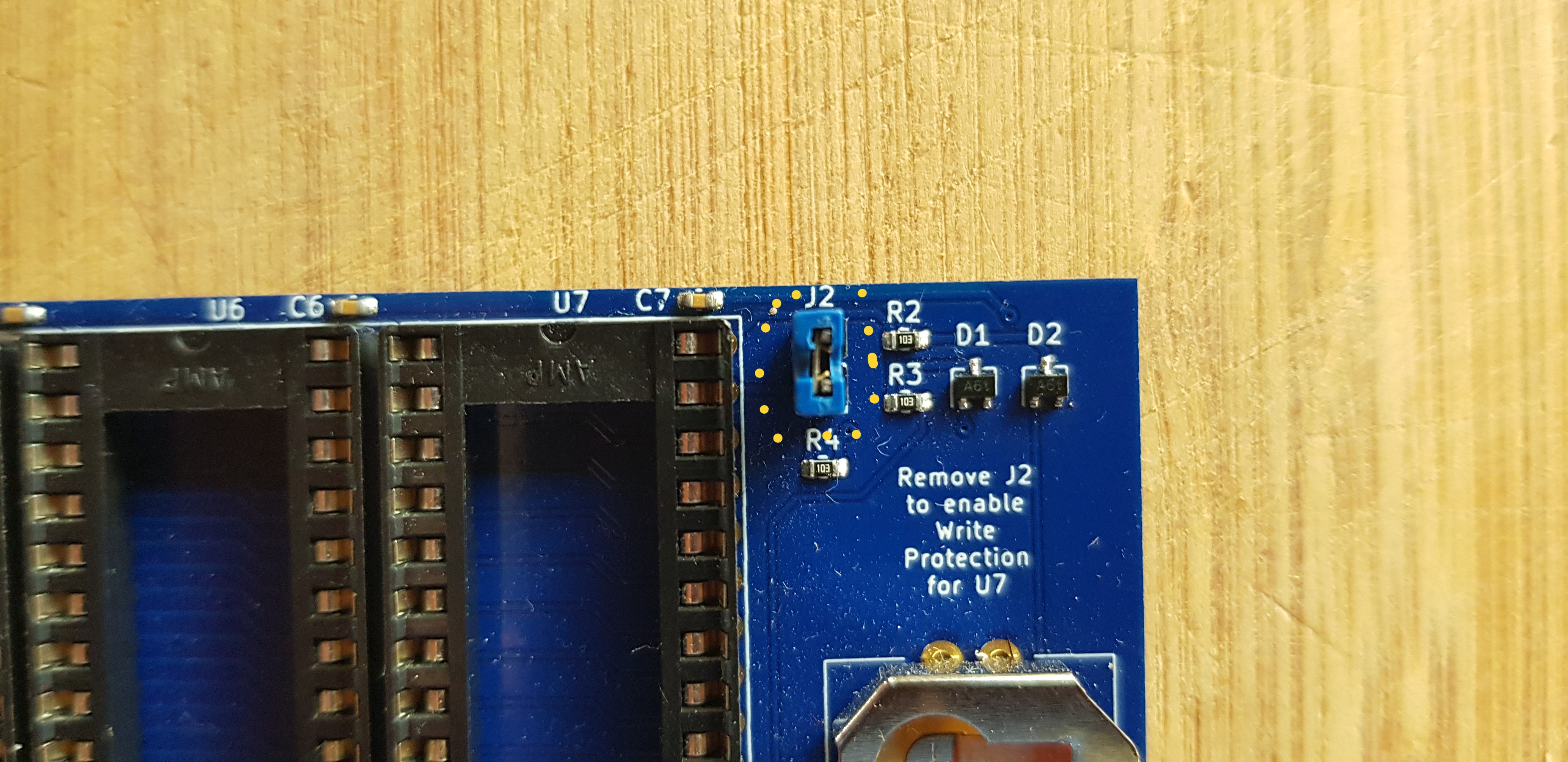 Close the J2 jumper pins (at the right side of the cartridge board) to remove the write-protection for ROM#7. Close the J2 jumper pins (at the right side of the cartridge board) to remove the write-protection for ROM#7. |
[!IMPORTANT] Once you have the J1 and/or J2 jumper pins properly closed on the cartridge board, the ROMs will be detected by the flashing program. If the jumper pins are open, the ROMs won't be recognized by the flashing program and your ROMn.BIN file(s) will not be flashed!
1.4. Final Update checklist for the Commander X16.
Please read through the following checklist before you commence running the CX16 update program, taking all the information you learned above:
1.4.1 Internal CX16 VERA update checklist:
- Is the version of the
VERA.BINcorrect? - Has the file been copied onto your SD card?
- Is the file named
VERA.BINin capital letters? - Do you have a jumper pin connector at your disposal?
You will need it to close the JP1 pins on the VERA board. - Are the JP1 jumper pins open on the VERA board?
- Have you understood why the JP1 jumper pins need to be closed and when it will be asked to close them?
- Have you understood why the JP1 jumper pins need to be opened again when the VERA memory has been updated?
- if you don't have any electronics experience, have you practiced to place a JP1 jumper cap on the JP1 jumper pins, and remove it, with the CX16 board powered off?
1.4.2 Internal CX16 SMC update checklist:
- Is the version of the
SMC.BINcorrect? - Has the file been copied onto your SD card?
- Is the file named
SMC.BINin capital letters? - Are the J5 jumper pins closed on the CX16 main board?
1.4.3 Internal CX16 ROM update checklist:
- Is the version of the
ROM.BINcorrect? - Has the file been copied onto your SD card?
- Is the file named
ROM.BINin capital letters? - Are the J1 jumper pins on the CX16 main board closed?
1.4.4 External CX16 ROMs update checklist:
- Are the version of the
ROMn.BINfile(s) correct? - Has(ve) the file(s) been copied onto your SD card?
- Have the file(s) been named
ROMn.BINin capital letters, with the n being a number from 1 to 7? - For the ROMs 1 to 6 on the cardridge, are the J1 jumper pins closed?
- For the ROM 7 on the cardridge, are the J2 jumper pins closed?
2. Run the CX16 update program.
-
Place the SD card in the CX16 (VERA) card slot.
-
Boot/Start your Commander X16 computer.
-
Type
LOAD CX16-UPDATE.PRGor pressF7on the keyboard (DOS"$") and put the cursor in front of the program, then pressF3on the keyboard (LOAD). -
Type
RUNor pressF5on the keyboard.
2.1 Main flow of the CX16 update program:
The update program is very user friendly and walks you through the different steps. Please find below a detailed description of the complete process.
For each component, the program will first detect each component and will search for the corresponding file names. It will read each file and check the contents before it will use the files to update your components. Once all the files have been checked, it will update your VERA card, then it will update the SMC and then the ROM(s). If there are ROMs on an external cardridge detected, then those roms will be installed first before the main CX16 ROM is updated.
2.1.1 Introduction and briefing screens
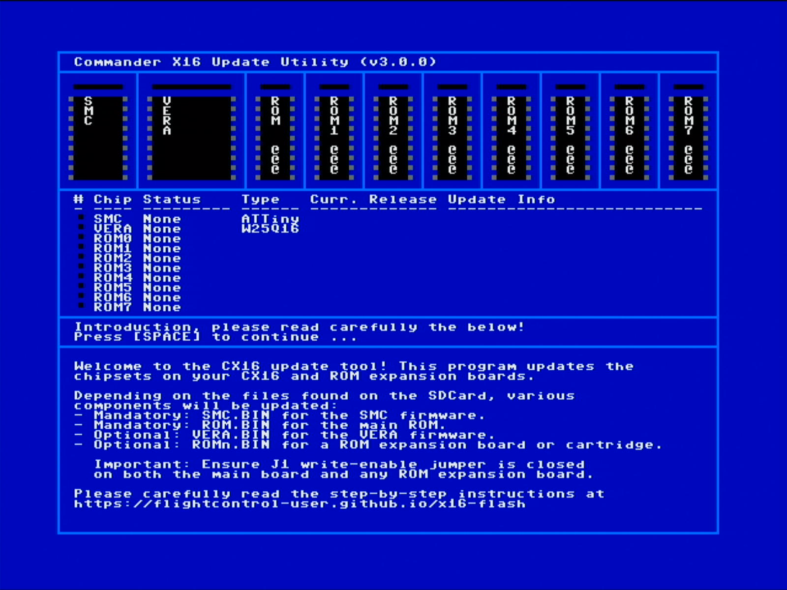 At program start, you will see an introduction screen, introducing the update process. Please carefully read the text at the bottom panel of the screen, and press SPACE to continue ... At program start, you will see an introduction screen, introducing the update process. Please carefully read the text at the bottom panel of the screen, and press SPACE to continue ... |
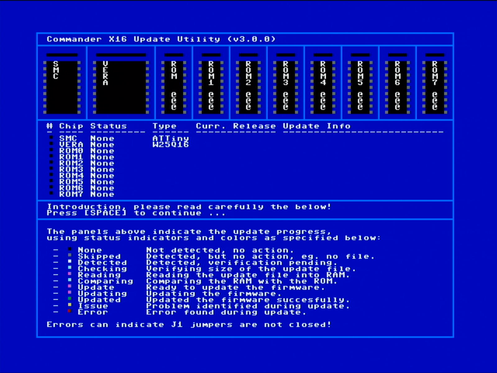 A second screen appears, which indicates the color schema used to indicate the update status of each component on your Commander X16 main board and/or your expansion cartridge board. Press SPACE to continue. A second screen appears, which indicates the color schema used to indicate the update status of each component on your Commander X16 main board and/or your expansion cartridge board. Press SPACE to continue. |
2.1.2 Component detection
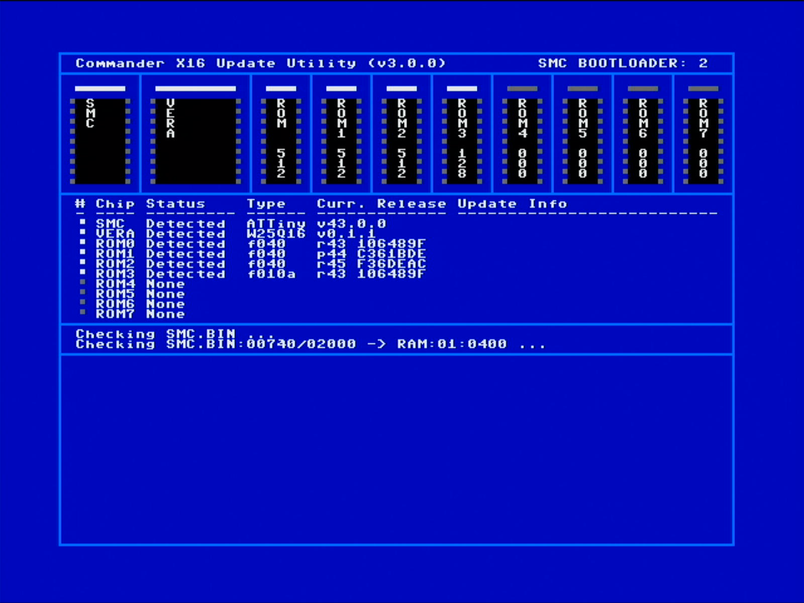 Next, the update program detects which components are upgradable and will validate which files are found on the SD card. The Commander X16 main board SMC, VERA and main ROM chip are detected, together with the external cardridge 7 ROM chips. Next, the update program detects which components are upgradable and will validate which files are found on the SD card. The Commander X16 main board SMC, VERA and main ROM chip are detected, together with the external cardridge 7 ROM chips. |
The Commander X16 main board SMC, VERA and main ROM chip are detected, together with the external cardridge 7 ROM chips.
Each component detected will be highlighted with a Detected status and a WHITE led. The capacity of each detected ROM is shown in KBytes.
Other components that are not detected are highlighed with a None staus and a BLACK led. These ROMs won't be considered for flashing.
2.1.3 File presence and validation for each detected component.
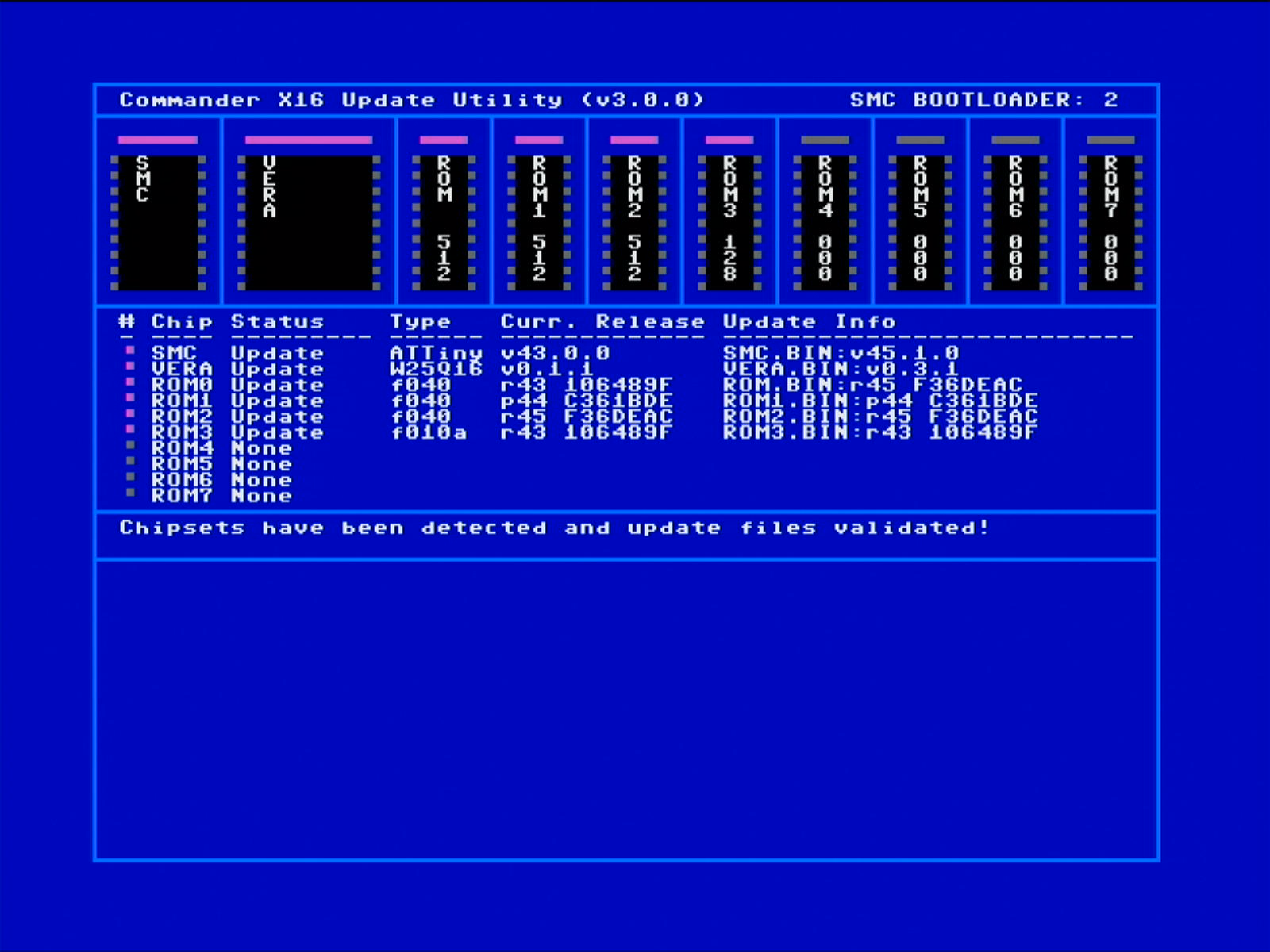 After component detection, the program will immediately search for file presence for each detected component and will validate it. The program will read each file and check on data size and any validation content to be used before flashing. After component detection, the program will immediately search for file presence for each detected component and will validate it. The program will read each file and check on data size and any validation content to be used before flashing. |
Detected and valid files will result in the status of the component in a PURPLE led and status
Update.Files that are not present, will result in the component not to be updated. The component will get a GREY led and status
Skipped.
2.1.4 Pre-Update conditions.
| Before the update commences, there are important conditions vaidated to ensure that any upgrade file or component compatibility risk or issues, potentially corrupting your CX16, are properly mitigated. |
- VERA and ROM versions are validated in terms of compatibility, to ensure that the ROM functions can be supported by the VERA card.
- SMC and ROM versions are validated, to ensure that they are "compatible": To avoid an SMC update corrupting your CX16 because it is not supportive or compatible with your ROM.
- File versions that are equal to the installed component versions will be skipped.
 When there are no issues, the user is asked for a confirmation to proceed with the update. Replying When there are no issues, the user is asked for a confirmation to proceed with the update. Replying N will cancel the update. Replying Y will proceed with the update! |
2.2 The CX16 update program updating your CX16 internal and external components
The CX16 update program will update each component that has status Update.
For each component, program will read the firmware data into RAM memory first, and will then use the data stored in RAM to update your CX16 component. The program guides you through the update process for each component in a very user friendly way, but mistakes are always possible, to please read carefully the below explanation. However, the component update process differs for each component type, so be aware!
2.2.1 The VERA update process
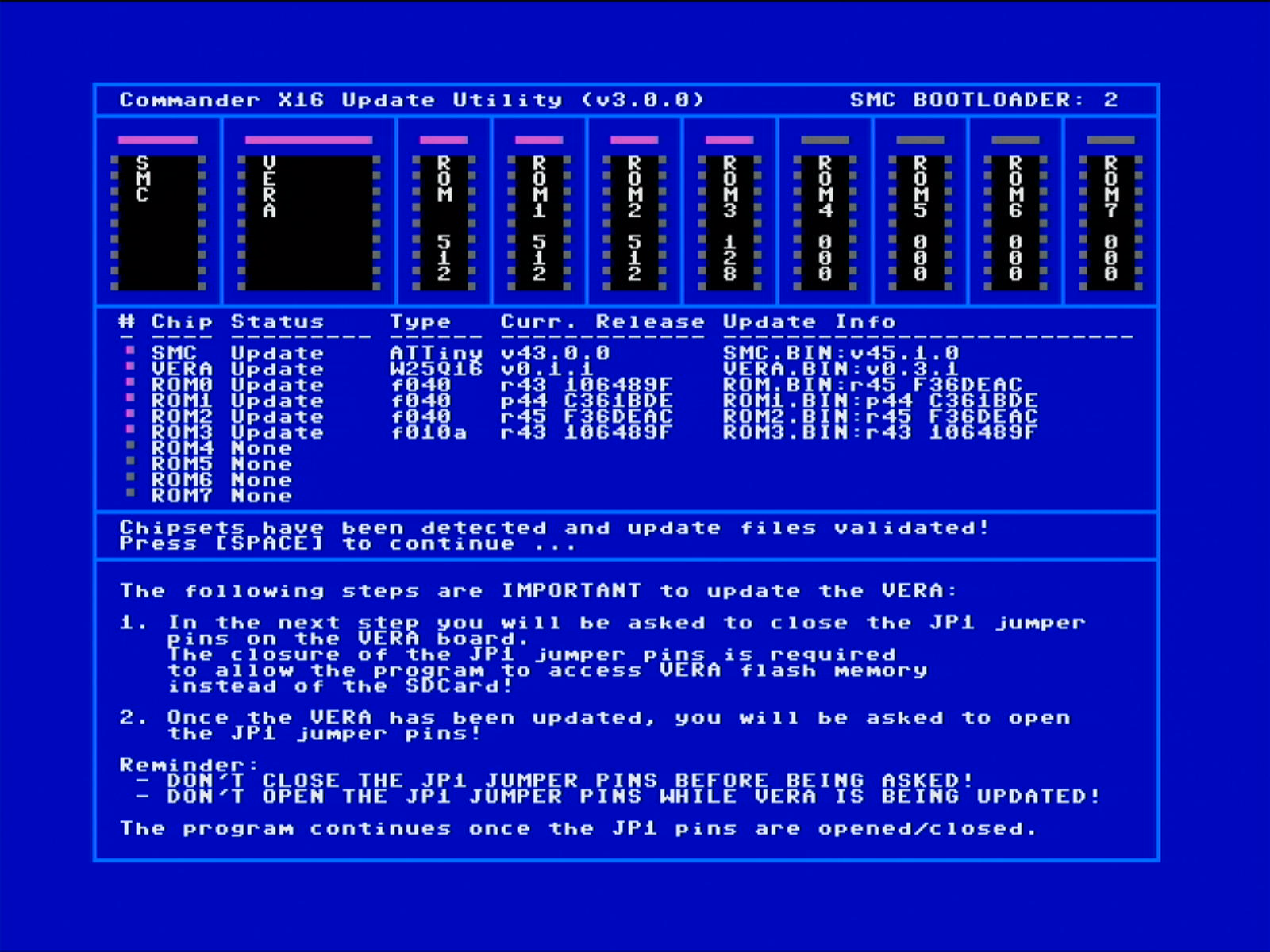 Before the VERA update starts, you will be presented with this important briefing, that explains the purpose of the JP1 jumper pins manual handing during the update process (Picture above). Press SPACE on the CX16 keyboard to continue. Before the VERA update starts, you will be presented with this important briefing, that explains the purpose of the JP1 jumper pins manual handing during the update process (Picture above). Press SPACE on the CX16 keyboard to continue. |
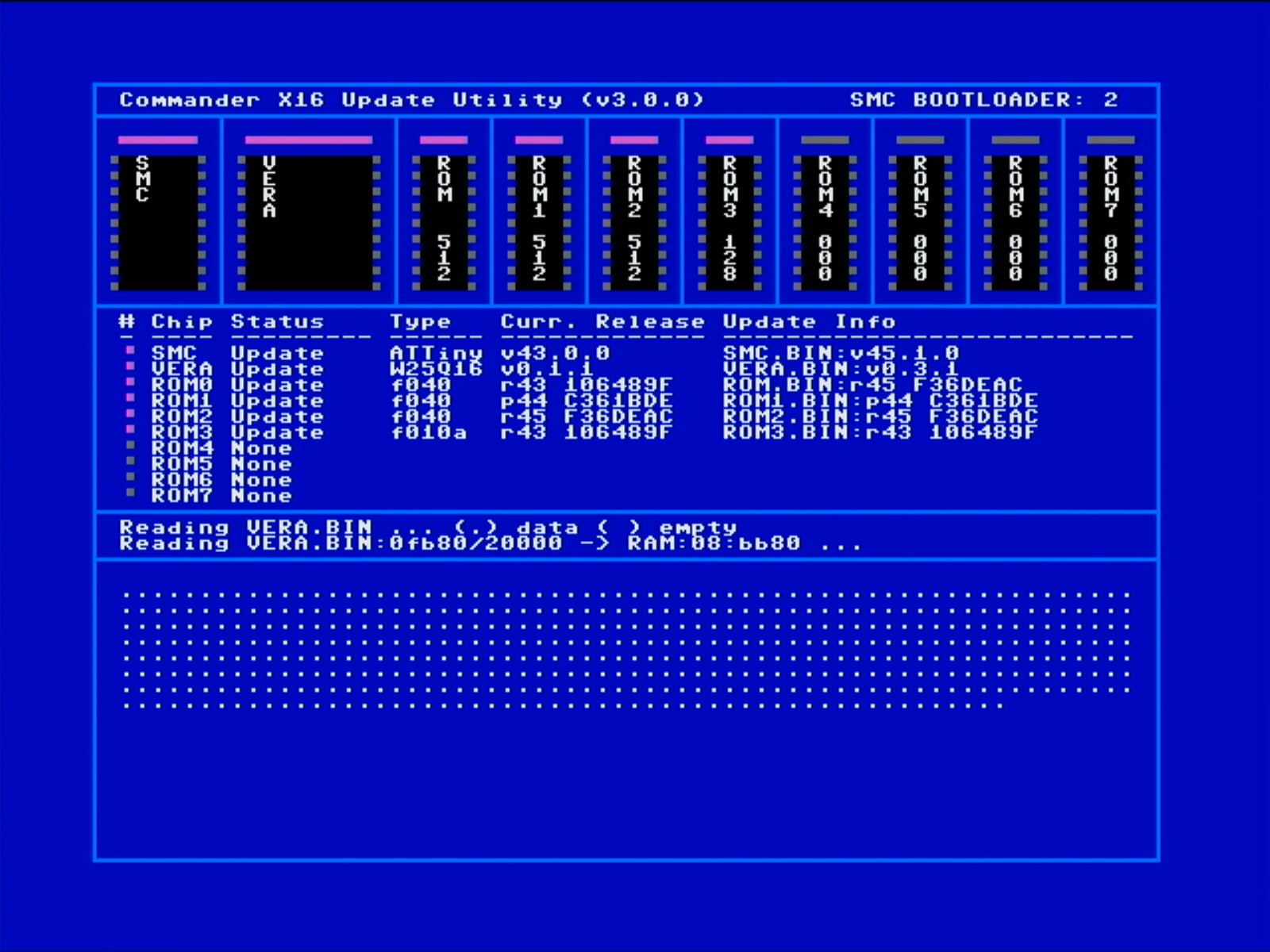 The program will then read the VERA.BIN file contents into RAM. The program will then read the VERA.BIN file contents into RAM. |
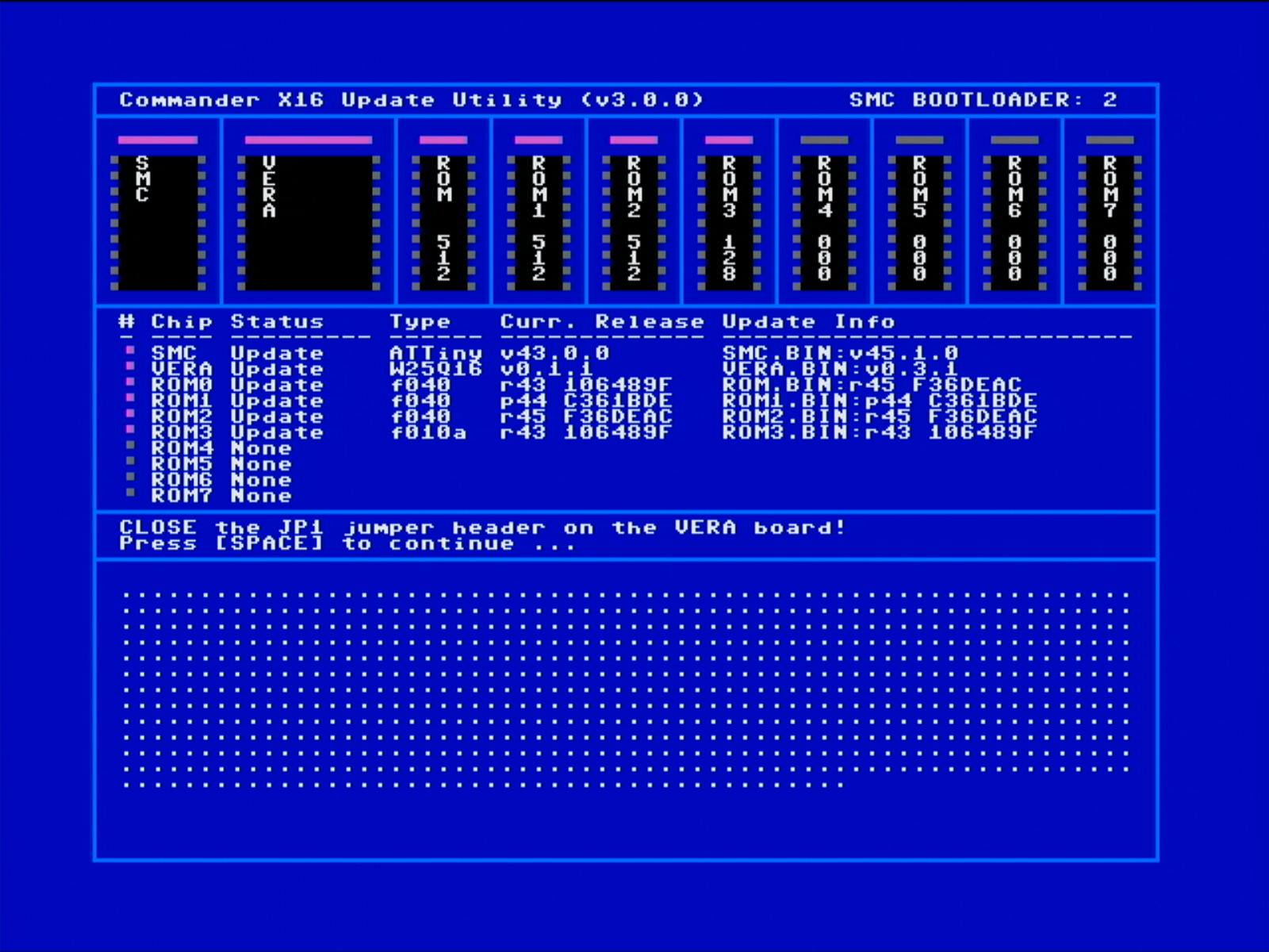 Then you will be asked to place the JP1 jumper cap onto the JP1 jumper pins, thus closing the JP1 jumper pins, in order to instruct VERA to direct its instructions to the SPI IC (instead of the SD card). Then you will be asked to place the JP1 jumper cap onto the JP1 jumper pins, thus closing the JP1 jumper pins, in order to instruct VERA to direct its instructions to the SPI IC (instead of the SD card). |
| Place the JP1 jumper cap, closing the JP1 jumper pins on the VERA board. Press SPACE to continue when finished. |
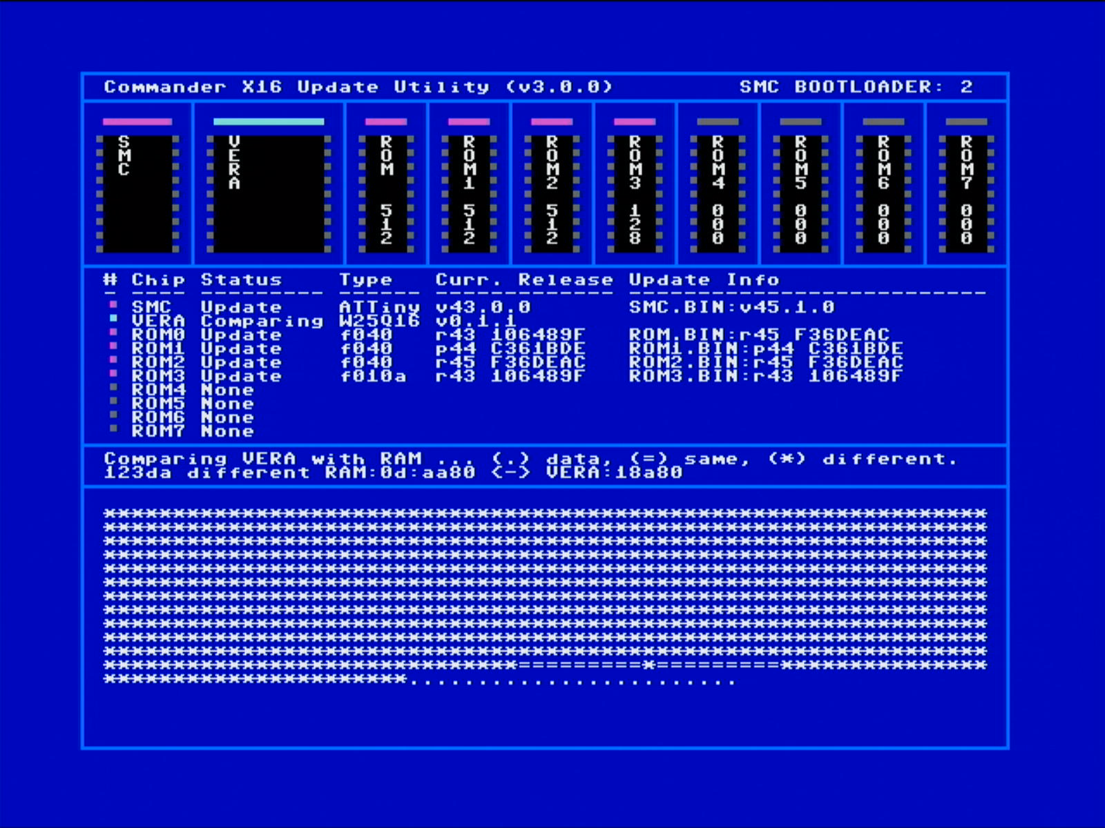 Before the program updates your VERA firmware, it will compare the contents of the current VERA firmware with the contents of the VERA.BIN from RAM. Before the program updates your VERA firmware, it will compare the contents of the current VERA firmware with the contents of the VERA.BIN from RAM. |
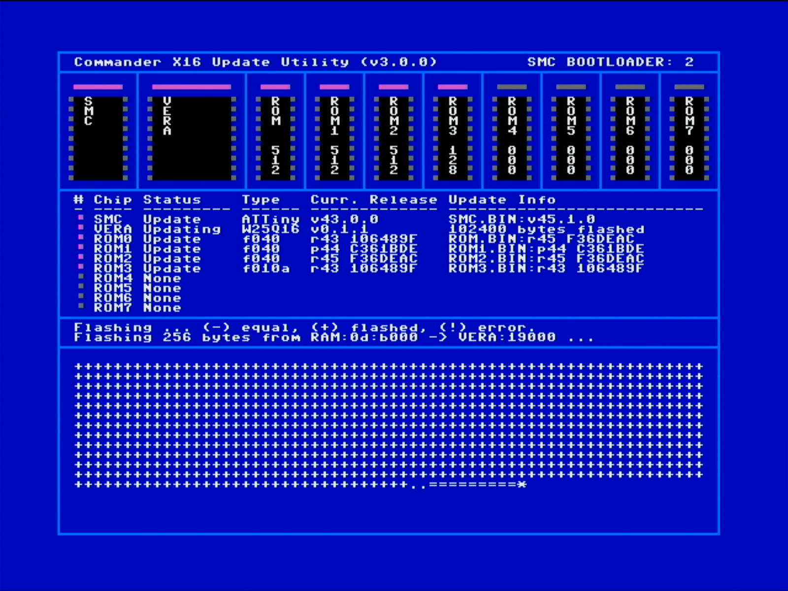 Once all the data has been compared, it will update your firmware if the compare results shows differences. Once all the data has been compared, it will update your firmware if the compare results shows differences. |
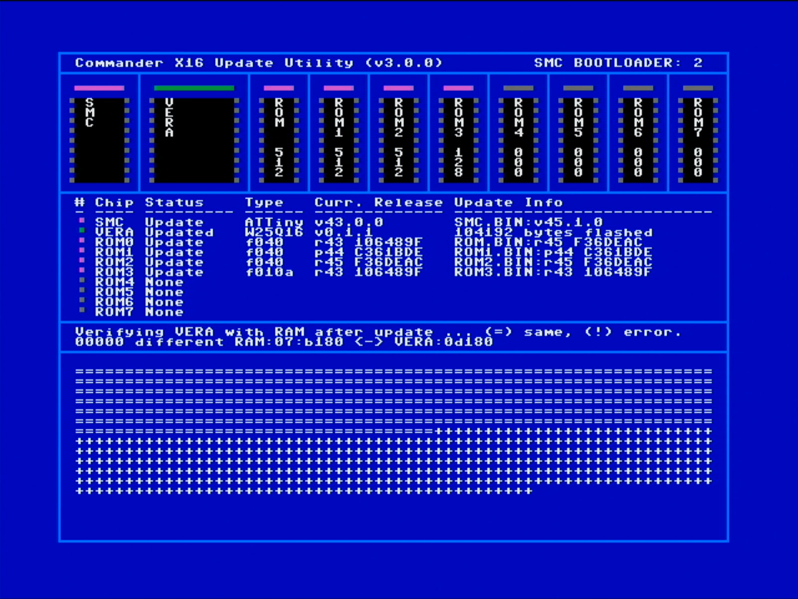 Once the program has flashed your new VERA firmware, the program will verify the contents of the new VERA firmware flashed with the RAM contents. The comparison result should be equal. Once the program has flashed your new VERA firmware, the program will verify the contents of the new VERA firmware flashed with the RAM contents. The comparison result should be equal. |
 When all VERA flashing and verification processes are complete, the program will ask you to remove the JP1 jumper cap from the JP1 jumper pins, thus opening the JP1 jumper pins to instruct VERA to direct its instructions back to the SD card. When all VERA flashing and verification processes are complete, the program will ask you to remove the JP1 jumper cap from the JP1 jumper pins, thus opening the JP1 jumper pins to instruct VERA to direct its instructions back to the SD card. |
| Remove the JP1 jumper cap from the JP1 jumper pins on the VERA board. Press SPACE to continue. |
When the comparison result is equal, the VERA led whill show a GREEN color and the status will show
Flashed.
2.2.2 The SMC update process
Once the VERA update process has finished, the SMC update starts.
[!WARNING] The SMC update process is one of the most critical phases updating your CX16. Ensure that you keep your device powered on at all times during this update process! Don't disconnect or power off the CX16 once the SMC update has been finalized. The complete CX16 program needs to execute completely till the end before the CX16 can be restarted!
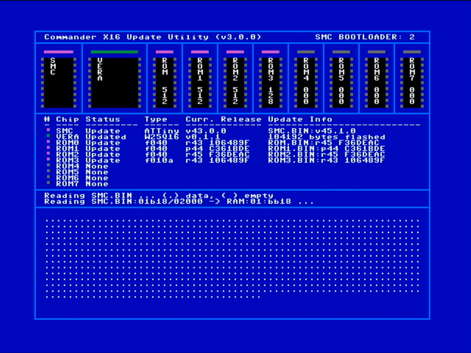 The program reads the The program reads the SMC.BIN into your CX16 RAM. |
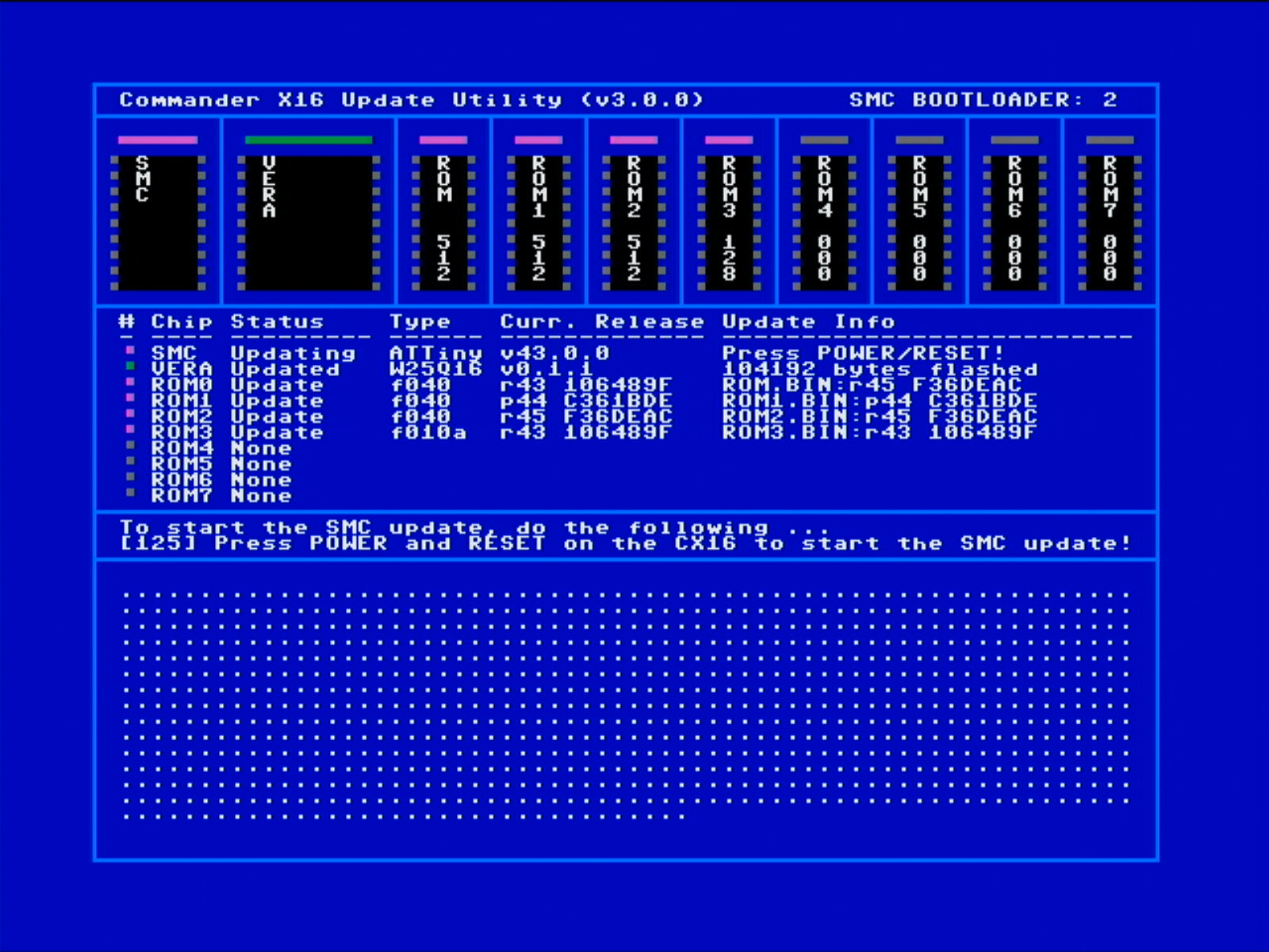 Next, the program asks you to press the Next, the program asks you to press the POWER and the RESET button simultaneously on the CX16 board. |
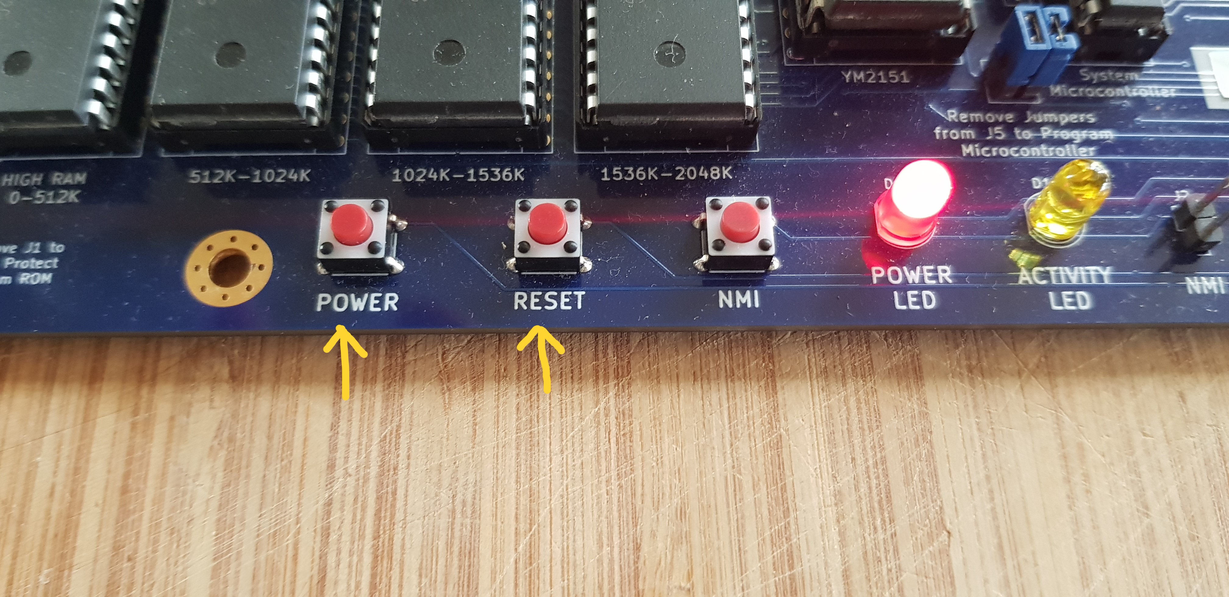 Perform this action on the CX16 board. (You can also press the POWER and RESET buttons on your (CX16) computer case if these Perform this action on the CX16 board. (You can also press the POWER and RESET buttons on your (CX16) computer case if these POWER and RESET buttons are wired onto the FP header on the main CX16 board.) |
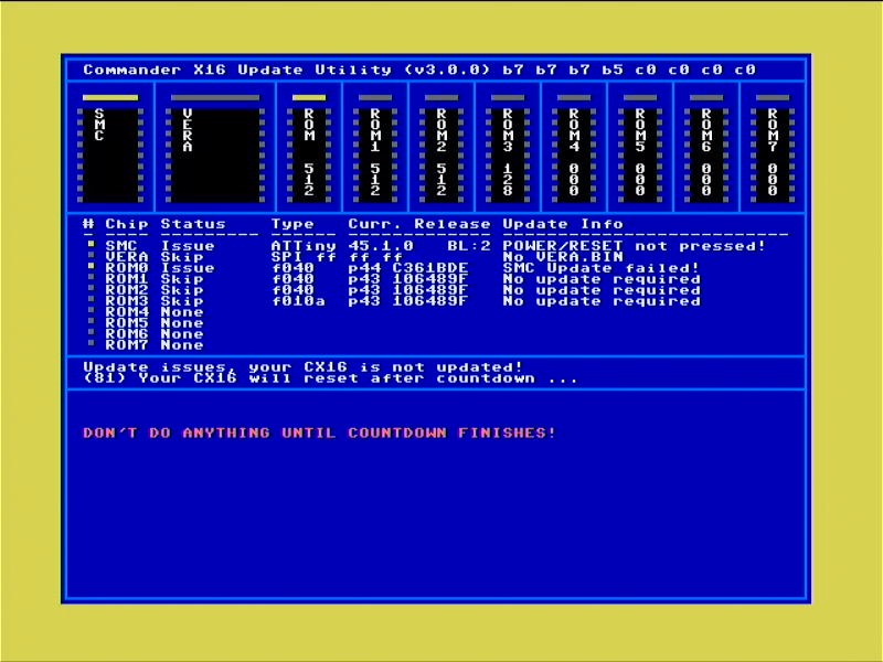 When the When the POWER and RESET buttons are not pressed in time (there is a countdown), the program will cancel the update of the SMC but will continue updating any other component. The update of the ROM will be skipped, though! The cancellation of the SMC update results in a reported issue, as the SMC and the ROM must be flashed together. |
| When POWER and RESET buttons are pressed, the program will update your SMC. Don't interrupt the process! It is essential at this stage that you don't shut down your CX16! | |
To ensure that your SMC has been properly updated, the SMC will show as a GREEN led and status
Updated.VERY IMPORTANT: Once your SMC is updated, you MUST wait till the end of the program to continue to update process, or your CX16 will be BRICKED!!!
2.2.3 The ROM update process
Once the SMC update process has been finished, the ROM update process starts. It will first update the ROMs that are on your external ISA card, before it updates your main CX16 RAM. Of course, if there isn't an external ROM expansion cardridge installed and/or no external ROMs are detected, the program will update your main CX16 ROM immediately.
The update of the main CX16 ROM is also a critical phase which you should not interrupt. Ensure you keep your CX16 powered ON!
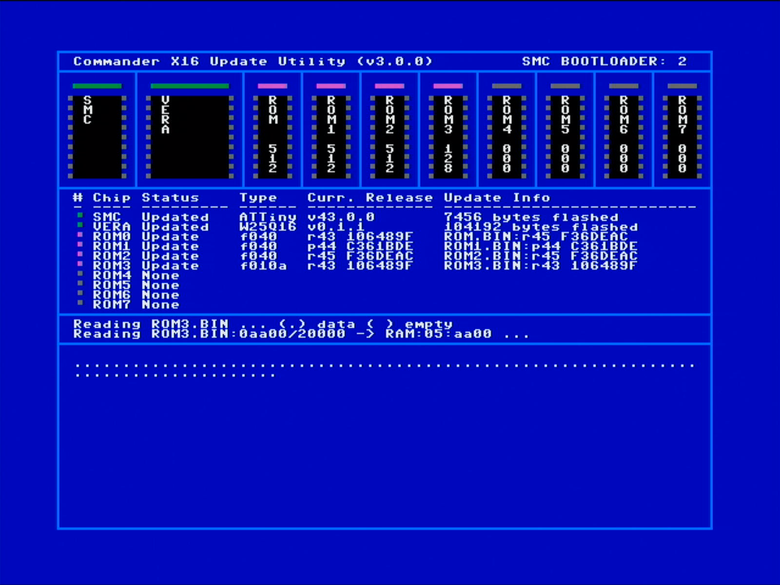 For each For each ROMn.BIN file found, the respective ROM wil be updated. The update process will start with the ROM with the highest number until the main CX16 ROM is updated. |
|
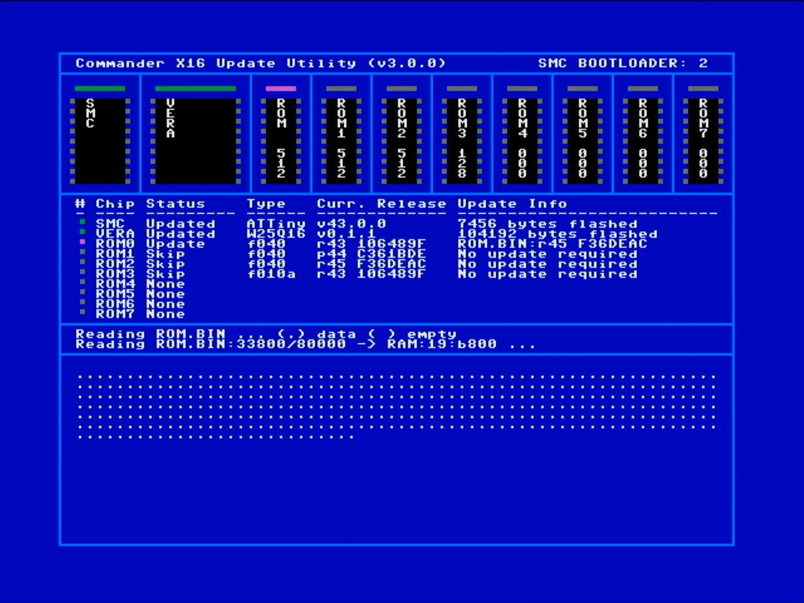 The loading process is seamless, if there is a file, each byte in the file is loaded into low and high RAM. The first $2000 bytes are loaded in low RAM, while the remainder of the The loading process is seamless, if there is a file, each byte in the file is loaded into low and high RAM. The first $2000 bytes are loaded in low RAM, while the remainder of the ROMn.BIN file is loaded in high RAM. Each $200 bytes loaded will be shown on the screen as a (.) in the memory matrix. Each row in the matrix represents $8000 bytes. A ROM can have a maximum of 512K, so there are maximum 16 rows possible to be shown in the matrix, and will be fully loaded into RAM on the Commander X16 before the update process starts! |
|
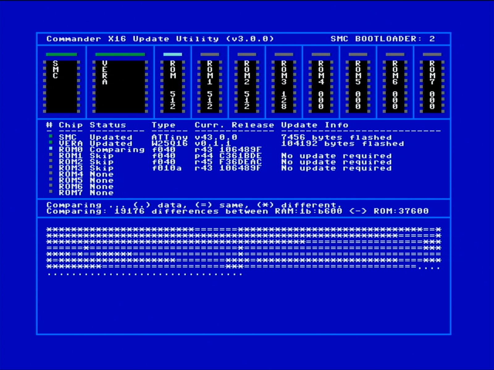 Once the Once the ROMn.BIN file has been loaded into RAM, the program will compare the RAM contents with the ROM contents. Data blocks not yet compared are shown with a (.). Data blocks which bytes are completely equal, are shown as (=), while data blocks which are different are shown with a (*) |
|
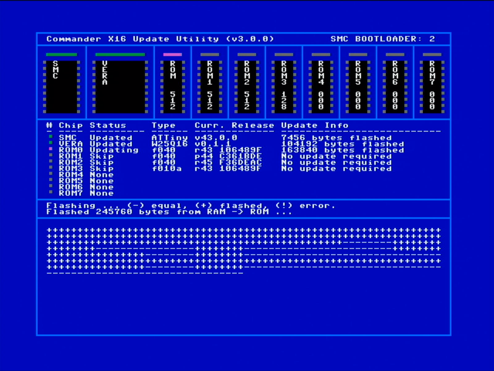 The update process is started if the comparison result shows differences between ROM and the The update process is started if the comparison result shows differences between ROM and the ROMn.BIN file from RAM. Each block is sequentially updated one by one. Once a whole block has been updated, the block is indicated with a (+). Equal blocks are in principle not updated, however, the ROM update process requires updates to be done in larger sectors. So if there are equal blocks in the same large sector, then these will also be updated again and will show with a (+) also. Sectors that are completely equal will show with a (-). If there is any error during the update process, then a (!) will be shown! |
Once the whole update process is finished, then the next
ROM.BINfile is read into internal memory. This process is repeated until the main CX16 ROM is updated with it's correspondingROM.BINfile!
2.3 Debriefing
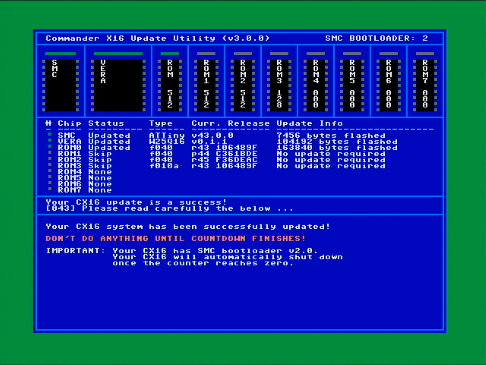 Once all your components are updated you should see a debriefing screen with a green border. Once all your components are updated you should see a debriefing screen with a green border. |
If you have updated your SMC, the debriefing screen will instruct you a specific process to follow to finalise the update. Depending on the boot loader version, which can be one or two, the exit procedure differs:
-
When your commander X16 contains bootloader one, you need to stay and wait patiently until the counter finishes to zero. Next you will be instructed to disconnect the power cable from your commander X16. Don't worry that process is perfectly fine. You won't be able to shut down your commander X16 because the power button will not be functional. Next you reconnect your power cable to the commander X16 and power up the computer.
-
When your commander X16 contains bootloader two, once the counter finishes to zero, the computer will automatically shut down. Just start the commander X16 with the power button.
3 ISSUES AND RESOLUTIONS
| Component | Issue | Resolution |
|---|---|---|
| VERA | No VERA.BIN | Place the correct VERA.BIN on your SD card. A valid VERA.BIN file must be lower than 128KB and may not be of size 0KB. |
| SMC | SMC no bootloader | When updating the SMC, a valid bootloader is required! You must resort to flash a bootloader onto your SMC using an external device. See the procedure under #4 Recovery procedures. |
| SMC | POWER-RESET buttons not pressed in time | Ensure that the POWER-RESET buttons are pressed on the CX16 board in time (before the counter drops to zero) |
| SMC | No SMC.BIN | Place the correct SMC.BIN on your SD card. A valid SMC.BIN file must not be larger than 2KB and may not be of size 0KB. The SMC.BIN file contains version and compatibility information, which is checked, so ensure you have a valid SMC.BIN file! |
| ROM | On-board CX16 ROM not detected. | Are the J1 jumper pins on the On-board CX16 closed? |
| ROM | External ROMs not detected on cardridge. | Are the J1 and J2 jumper pins on the On-bard CX16 closed? Are the values you see at the top of the screen B5, B6, B7? |
| ROM | No ROM.BIN | Place the correct ROM.BIN on your SD card. A ROM.BIN may vary in size, but must always be larger than 0KB. The size of the ROL.BIN must be equal to multiples of $4000 bytes! |