 smurfy
commented
10 years ago
smurfy
commented
10 years ago schematic looks good now. in my opinion :) and it works on my digispark that way
Open mfc123 opened 10 years ago
smurfy
commented
10 years ago schematic looks good now. in my opinion :) and it works on my digispark that way
 JonathancalderonIL
commented
10 years ago
JonathancalderonIL
commented
10 years ago smurmy can you take some photos of your setup ?
JonathancalderonIL
commented
10 years ago just got most of the parts i needed (part from the attiny)
going to use this guide http://www.instructables.com/id/The-Idiots-Guide-to-Programming-AVRs-on-the-Chea/?ALLSTEPS
to program the attiny85 using USBASP and arduino IDE.
hope to report back soon...

 nilsheidorn
commented
10 years ago
nilsheidorn
commented
10 years ago My stuff has not yet arrived, so good luck and keep us updated :-)
Nils
JonathancalderonIL
commented
10 years ago smurfy, have you seen this ? http://projectsfromtech.blogspot.co.il/2014/01/i2c-hc-sr04-sonar-module-attiny85-i2c.html this guy say "You need to burn your ATtiny85/45 to 8MHz. This is important for stable I2C communication" @rambo say the same... https://github.com/rambo/TinyWire as long as your code uses his tinywire lib i would think we need to burn the attiny to 8mhz first did you do this with yours ?
smurfy
commented
10 years ago My implementation of accessing the sonar is a bit different than in your linked article but the result should be the same.
For the clockspeed, digispark runs with 16mhz, directly on the raw atiny85 i flashed it with arduino Ide with 1mhz, 8mhz and 16mhz.
But i'm not sure that does the trick and sets the actual fuses. I tested with the blink example too, if i flash it with 8 or 16 mhz the blink is much slower. (the led stays longer on/off) not sure if thats an indication that while i flashed for 8 mhz, the internal clock still works on 1mhz or not.
I'm a bit reluctant setting the fuses myself, because i also found a lot of results that it could make your attiny unflashable (except with a high voltage flasher i don't own).
smurfy
commented
10 years ago Ok based on this You also need to use the "write bootloader" method from the menu (after choosing the 8mhz variant) I did not do that.
i'm not sure if i have the time today but i will test it for sure tomorrow. with 8mhz.
Edit: and because you asked:  attiny and resistors on the breadboard, my test arduino mega in the background and flying around also with wires is my digispark :) ah and in the front the sonar :) And far in the back the board where i will put everything once it works :)
 rambo
commented
10 years ago
rambo
commented
10 years ago Write/burn bootloader in Arduino IDE with the attiny cores will only sets fuses, this is safe to do (it won't disable the reset pin which would be the way to make the attiny unprogrammable except with HV-programmer).
For this you will need some ISP-programmer (USBASP, or AVRISPmkII, or something), this will most definitely mess up the USB-serial "soft-bootloader" that digispark comes with (a "real" one is in a separate memory space, but attinys do not support that, so a soft-bootloader needs to be smart enough to not overwrite itself...)
TinyWire requires at least 8Mhz and even then it will stretch the clock, your master needs to be able to deal with that (if the master is and ATMega with TWI hardware you're good, otherwise there might be gotchas [especially with bit-banged implementations]).
Also the default ultrasound library is blocking during the pulse, this is a big no-no for TinyWireS, so you will need to make your own non-blocking interrupt-driven version, unfortunately attiny85 does not have input-capture hardware, that would have made this really easy.
smurfy
commented
10 years ago @rambo
Thanks for clearing up some things.
The digispark is my development platform, because its much easier to flash than a standalone tiny. They ship their own version of arduino ide and i never planed to flash/change fuses on it. You even flash the digispark different because of it's bootloader.
The board we want to use the attiny with, uses an atmega 2560 (same as the arduino mega)
My Ultrasound implementation does use Interrupts to not block the i2c communication. As you mentioned, the tiny only has one external interrupt which is already used by tinywire so i use the "PinChangeInterrupt library" for easy access to the internal interrupts and distinction of which pin changed.
rambo
commented
10 years ago PinChangeInt does use external hardware interrupts (though those are port specific and the library needs to check the pin in question) but that's beside the point.
I wonder what clock speed the digispark runs at, I think it needs to be over 12MHz to be able to bit-bang USB. In any case you can try TinyWireS in it too, choose the digispark board from boards menu and do not "burn bootloader" (I guess I should at least download their version of ArduinoIDE so I can check the settings they use...)
The Mega2560 has proper TWI so all good there.
The sonar library: You will want to use separate handlers for HIGH and LOW ends of the pulse, this avoids the (slow) diditalread call, or use direct register addressing but that's not portable (the library figures out the registers at attach time and then works very quickly). Paul (of Teensy fame) made digitalWriteFast (and maybe digitalReadFast, not 100% sure about that though) additions to at least the teensy patches, not sure if those are in mainline Arduino yet, they figure out the registers etc compile-time and thus compile down to single cycle operation (they do have some caveats like can only use constant pin numbers etc).
I have also a forked pinchangeint library for passing more data to the handler, this sketch ought to give a good example of why I would want to do that: https://github.com/rambo/Arduino_rcreceiver/blob/master/Arduino_rcreceiver.ino
I also have a fork of the arduino-tiny core, for adding features etc (like support for attiny1634 which is both better and cheaper than the older attinys, a bit larger though which might be a problem in some cases).
smurfy
commented
10 years ago You will want to use separate handlers for HIGH and LOW ends of the pulse,
ok, i will check that as soon i got time, thanks for the tip.
I wonder what clock speed the digispark runs at,
the digispark runs at 16mhz without crystal, which is not 100% 16mhz but it seams to work just fine. It also syncs it's clock with usb if connected to it.
I also have a fork of the arduino-tiny core,
i found your repository too, while searching for the source of the atiny-core library. but choose to link to the upstream version.
why use an attiny1634 over an atmega328p for example? Price? Power consumption? What i like at the attiny85 is that its really small :)
rambo
commented
10 years ago It also syncs it's clock with usb if connected to it.
That is a nifty trick
why use an attiny1634 over an atmega328p for example? Price? Power consumption?
Especially price (also power consumption), if one doesn't need some of the hardware features only available in the ATMega -series (though even then I would go for XMega unless I was looking for maximum Arduino compatibility). And in fact tiny1634 has more ADC channels the mega328 so if one would need those (like for capaticative touch interfaces, tiny1634 has qtouch support as well). Also inside the tiny family there's a bunch of chips with one or two advanced niche features that are not found in the mega328 (quite possible are in other chips of the family but I haven't compared those so much)
Anyway, I'll be mostly away from computer for a week now, good luck with your project.
 bektorkhan
commented
10 years ago
bektorkhan
commented
10 years ago @smurfy all IC's especially uP need one or several decoupling capacitors on each power pin to ensure smooth and enough power to keep the internal power from dropping below it's specs under heavy load causing the uP to trigger a brownout reset.
So electrically close to the power pins you place a 33-100 nF capacitor, as an energy buffer/filter.
Below is my schematic on a Attiny85 board, with testpads for InCircuitProgramming.
A board for could be as small as 10x12mm SingleSided without power regulator, but current gen FC's have 3.3V i2c, so one should design for that! So then it should be double sided to keep size down.

smurfy
commented
10 years ago @bektorkhan many infos i need to process :)
About the 3.3V i2c, i also seen some boards using 3.3V but the crius v2 for example uses 5v. Same goes for the witespy board i own (it also supports 3.3v i2c)
I know about the brownout problem, so i usually use something like this, shouldnt this be enougth?
bektorkhan
commented
10 years ago It's to much and the internal high frequency impedance is to high.. This is what you need since your holemounted: http://www.digikey.com/product-detail/en/K104K15X7RF5TL2/BC1084CT-ND/286706 Any ceramic capacitor 16V or higher 47nF or more , ceramic capacitors are not polarized! Most I2C sensors are 3.3V that's why you need pullup resistors on the bus to ensure that a 5V uP a logic high level above 2.8 V, but the noisemargin is bad and there's more risk of bus errors, I read somewhere that AtMega 2560 has built-in pullup on it's I2C bus, so that's why all sensors need levelshifting from 5V to 3.3V. Be aware to keep the i2c network as short as possible and away from power cables and antennas, or there could be so many bus errors the FC will crash.
smurfy
commented
10 years ago Ok, after "installing bootloader" @ 8mhz and reflasing the attiny works like a charm and the i2c communication works too.
I did some more tests:
JonathancalderonIL
commented
10 years ago hey guys. my laptop and iphone passed away so i havent been around (restoring data all weekend) but while installation.... got the time to solder my long planned Attiny85 programing board.
as you can see i have 6 and 10 pins for different pogramers i have (the one connected is the best cheap made in china one) , 8 pins microcontroller socket, 2 rows of headers on the sides for extra conections and 5V JST input. did most of the connection on the bottom but havent finished yet. as you can see the only thing missing is the Attiny85 wich didnt get here yet. hope to have it in the next cuple of days and update on the results.
smurfy is there any change in the MPNG code needed to be done before connecting the attiny and sonar to it ? or just enable the sonar using mission planner ? i think i am going to be powering this with 5V unless someone think 3.3V would get better results.
Jonathan


JonathancalderonIL
commented
10 years ago just finished soldering the 6 pin connector on from the USBASP to the chip socket.
hopefully tomorrow i'll get the attiny and start testing...
sorry about all the pictures i upload i just like it when others do it so i can learn so i started doing it myself...

Jonathan
smurfy
commented
10 years ago is there any change in the MPNG code needed to be done before connecting the attiny and sonar to it ?
yes. you need the patch from here: http://www.megapirateng.com/forum/viewtopic.php?f=4&t=47
JonathancalderonIL
commented
10 years ago hi smurfy when i try to flash the code i get this errors. what did i do wrong ?
C:\Documents and Settings\אלונה\My Documents\Arduino\libraries\PinChangeInterrupt\PinChangeInterrupt.cpp:50: error: 'NUMBER_PIN_CHANGE_INTERRUPT_HANDLERS' was not declared in this scope
C:\Documents and Settings\אלונה\My Documents\Arduino\libraries\PinChangeInterrupt\PinChangeInterrupt.cpp: In function 'void attachPcInterrupt(uint8_t, void (*)(), uint8_t)':
C:\Documents and Settings\אלונה\My Documents\Arduino\libraries\PinChangeInterrupt\PinChangeInterrupt.cpp:76: error: 'digitalPinToBitMask' was not declared in this scope
C:\Documents and Settings\אלונה\My Documents\Arduino\libraries\PinChangeInterrupt\PinChangeInterrupt.cpp:80: error: 'CHANGE' was not declared in this scope
C:\Documents and Settings\אלונה\My Documents\Arduino\libraries\PinChangeInterrupt\PinChangeInterrupt.cpp:84: error: 'FALLING' was not declared in this scope
C:\Documents and Settings\אלונה\My Documents\Arduino\libraries\PinChangeInterrupt\PinChangeInterrupt.cpp:88: error: 'RISING' was not declared in this scope
C:\Documents and Settings\אלונה\My Documents\Arduino\libraries\PinChangeInterrupt\PinChangeInterrupt.cpp:104: error: 'pcint' was not declared in this scope
C:\Documents and Settings\אלונה\My Documents\Arduino\libraries\PinChangeInterrupt\PinChangeInterrupt.cpp:105: error: 'NUMBER_PIN_CHANGE_INTERRUPT_HANDLERS' was not declared in this scope
C:\Documents and Settings\אלונה\My Documents\Arduino\libraries\PinChangeInterrupt\PinChangeInterrupt.cpp: In function 'void detachPcInterrupt(uint8_t)':
C:\Documents and Settings\אלונה\My Documents\Arduino\libraries\PinChangeInterrupt\PinChangeInterrupt.cpp:266: error: 'digitalPinToBitMask' was not declared in this scope
C:\Documents and Settings\אלונה\My Documents\Arduino\libraries\PinChangeInterrupt\PinChangeInterrupt.cpp:274: error: 'pcint' was not declared in this scope
C:\Documents and Settings\אלונה\My Documents\Arduino\libraries\PinChangeInterrupt\PinChangeInterrupt.cpp:275: error: 'NUMBER_PIN_CHANGE_INTERRUPT_HANDLERS' was not declared in this scope
C:\Documents and Settings\אלונה\My Documents\Arduino\libraries\PinChangeInterrupt\PinChangeInterrupt.cpp: In function 'void detachPcInterrupt(uint8_t, void (*)(), uint8_t)':
C:\Documents and Settings\אלונה\My Documents\Arduino\libraries\PinChangeInterrupt\PinChangeInterrupt.cpp:315: error: 'digitalPinToBitMask' was not declared in this scope
C:\Documents and Settings\אלונה\My Documents\Arduino\libraries\PinChangeInterrupt\PinChangeInterrupt.cpp:319: error: 'CHANGE' was not declared in this scope
C:\Documents and Settings\אלונה\My Documents\Arduino\libraries\PinChangeInterrupt\PinChangeInterrupt.cpp:323: error: 'FALLING' was not declared in this scope
C:\Documents and Settings\אלונה\My Documents\Arduino\libraries\PinChangeInterrupt\PinChangeInterrupt.cpp:327: error: 'RISING' was not declared in this scope
C:\Documents and Settings\אלונה\My Documents\Arduino\libraries\PinChangeInterrupt\PinChangeInterrupt.cpp:337: error: 'pcint' was not declared in this scope
C:\Documents and Settings\אלונה\My Documents\Arduino\libraries\PinChangeInterrupt\PinChangeInterrupt.cpp:338: error: 'NUMBER_PIN_CHANGE_INTERRUPT_HANDLERS' was not declared in this scope
C:\Documents and Settings\אלונה\My Documents\Arduino\libraries\PinChangeInterrupt\PinChangeInterrupt.cpp: In function 'void PCINTX_common(uint8_t, volatile uint8_t&)':
C:\Documents and Settings\אלונה\My Documents\Arduino\libraries\PinChangeInterrupt\PinChangeInterrupt.cpp:393: error: 'pcint' was not declared in this scope
C:\Documents and Settings\אלונה\My Documents\Arduino\libraries\PinChangeInterrupt\PinChangeInterrupt.cpp:394: error: 'NUMBER_PIN_CHANGE_INTERRUPT_HANDLERS' was not declared in this scopeDid you select attiny85 as board?
JonathancalderonIL
commented
10 years ago yes. attiny85 (internat 1mhz clock)
smurfy
commented
10 years ago Hm quite strange, i use Arduino 1.0.5 with the documented libraries and it compiles just fine. If i compile it for the wrong board it throws errors with the tinywire lib not PinChangeInterupt.
JonathancalderonIL
commented
10 years ago as i read this is someting to do with the scope of wich the Variables are declared. http://arduino.cc/en/Tutorial/Variables i am using 1.0.5 r2
cant seem to find a fix on google and my C skills are about 0 so,,,, helpppp
JonathancalderonIL
commented
10 years ago fixed, i was using the wrong attiny boards.txt i used an old one to check my "blink" example to make sure my programmer is working corectly. going to flash now...
smurfy
commented
10 years ago Ok, great. Make sure you do:
JonathancalderonIL
commented
10 years ago OK.... got the attiny compiling OK now i am having problems with the patching of MPNG the instractions at http://www.megapirateng.com/forum/viewtopic.php?f=4&t=47 are not compatible with 3.0.1 r4 probably... i cant get it to compile. are you doing this release ? can you ZIP your release and upload it ?
thanks.
@SirAlex would this be included some time on the next release ?
JonathancalderonIL
commented
10 years ago In the mean time soldered a small attiny85 socket and few headers to go on the quad
Looks bad but working...
I think ill pass on the 4.7k resistors at this stage...
@smurfy have you seen HC-SR05 ,is there any differance from the 04 one ?

JonathancalderonIL
commented
10 years ago @smurfy i am about to give up on this.... the MPNG code changes are not working for me and wont compile. there is no proper way to check if the sonar with Attiny working. everytime i connect the VCC SDA SLA GND to my multiwii board i get arming errors...
how should i handle all this ?
smurfy
commented
10 years ago hm, if you connect vcc and gnd to the tiny, does the sonar do some noises?
JonathancalderonIL
commented
10 years ago if i put it in my ear i hear hmmmmm and BZZZzZZZ should it be loud? i can hardly hear it,,, Plus my MPNG Code is not compiling ...
smurfy
commented
10 years ago I hope i will find time to check the mpng code.
JonathancalderonIL
commented
10 years ago Cybergen from MPNG forum uploaded his 3.0.1 r4 and they compile OK
after i do all the connection to the board and enable sonar i get this on my test sonar terminal

i have tried disconnecting the VCC from the SDA SLA output and then i get this

any ideas ?
smurfy
commented
10 years ago i'm currently have no working FC, did you flash bootloader and software to the tiny with 8mhz?
JonathancalderonIL
commented
10 years ago yes i did. do you remember what kind of results where you getting on teminal test when it worked ? what happend to your FC ?
smurfy
commented
10 years ago I share my hobby with my flat mate, we had an witespy board for our copter and a crius v2 for testing and a bixler.
problem is we managed to brake off the usb from the witespy ez3 board :) now the crius is in the copter. :)
I did all my tests with my atmega board. i will try to get the witespy ez3 board working again to use this for my tests.
JonathancalderonIL
commented
10 years ago Me too share the hobby with my mate. We have few tricopters with kk2 and a quad with multiwii. Bixler and skyhigh with tornado osd. Few more petrol planes...
Can't you solder the USB back on ?
i have shared my results with Cybergen on the MPNG forum hoping he have an idea of what got wrong...
JonathancalderonIL
commented
10 years ago @smurfy on your photo (https://camo.githubusercontent.com/e3245f5925b5034992da14d71cf65b92c6a611d8/68747470733a2f2f692e696d6775722e636f6d2f5061567466376f2e6a7067) there is somting connected to PIN 6 of the Attiny... what is that.. ?
smurfy
commented
10 years ago Can't you solder the USB back on
we tried, but first try was not successfull, we will try again. also the ftdi approach did not work the first time. Another problem was, not sure if we sapped the board or something, after arming the board the accelometer/gyro seams to bugg and the horizon starts to drift.
to PIN 6 of the Attiny... what is that
thats for programming. i used the 3 red and the one orange unflexible wires to get MISO, MOSI, SCK and RESET in one row, for easier connecting it to my arduino to flash it.
Sorry for all the wires :) some are for programming, some are going to the actual tiny, some are going to the digispark.
I you could try to verify your connections with my superb ascii art i added a while back to my source:
HC-SR04:
|-------------
|( ) ( )|
--------------
1 2 3 4
(1) VCC -> VCC 5V
(2) TRIG -> Pin 2 on Attiny85 (PB3)
(3) ECHO -> Pin 3 on Attiny85 (PB4)
(4) GRD -> Ground
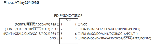
Attiny85:
1 |--U--| 8
2 |-----| 7
3 |-----| 6
4 |-----| 5
(1) RESET -> nothing
(2) PB3 -> TRIG on HC-SR04
(3) PB4 -> ECHO on HC-SR04
(4) GND -> Ground
(5) PB0, SDA -> SDA of the I2C Bus
(6) PB1 -> nothing
(7) PB2, SCL -> SCL of the I2C Bus
(8) VCC -> VCC 5V or 3.3Vi have worked with your ascii art :-) but if you remmember https://github.com/MegaPirateNG/ardupilot-mpng/issues/32#issuecomment-49151115 schematic, there is a VCC line going to the SCL and SDA (with pullup resistors) if i dont use them do i still need to power the SCL and SDA with VCC 5V ?
smurfy
commented
10 years ago if i dont use them do i still need to power the SCL and SDA with VCC 5V ?
no
JonathancalderonIL
commented
10 years ago ok so then i dont get the error but still get
sonar: 0 cm Health: 0 is there a specipic sonar i need to choose from in mission planner ?
JonathancalderonIL
commented
9 years ago @smurfy any news about this ? i went and got APM for my quad and fling very well. still would love to have sonar on it...
 evil-m
commented
8 years ago
evil-m
commented
8 years ago Hey @JonathancalderonIL , did you managed to get your hc-sr04 sonar working with the @smurfy 's code? I'm new to the mpgn comunity, I know that for now the development is aiming to the 32bits controllers, but it would be cool to have this feature working since there are lots of good enough 8bits flight bords around with reasonable price for the beginners, I have the RCTimer Crius All In One Pro V2. Well, I burned the code to the attiny85, with 8mhz internal clock set and put the 4.7k pull up resistors for the scl and sda lines, after this I tested the i2c bus on the attiny85 through some arduino code to debug it and see if it was working, it seems to be working good, altough I wasn't able to make it work with the patch Cybergen posted. I noticed that when using the patched code from Cybergen I got lots of i2c errors on mission planner (under satuts -> i2cerrors) when I enable the sonar. I think the problem is not with the hcsr04_i2c_attiny85 code, but with the driver on the mpng 3.0.4-R4. I'll try codding something myself to work with the sonar on the i2c without having all the errors I get with the patch from Cybergen. Did you managed to get it working? I ended up getting the same results you said: sonar: 0 cm Health: 0
Cya!
smurfy
commented
8 years ago @evil-m sorry, i currently have no time for the hobby :(
I think the main problem is, that the i2c bus is quite full. Because the boards MPNG supports use i2c for all sensors. that could explain the i2c errors.
Without the patch (or another) i2c sonars are not supported by the ardupilot code. (the classes exist but are not wired up). I never tested my "device" with mpng, i only used the ardupilot sonar code in a simple test sketch (https://github.com/MegaPirateNG/ardupilot-mpng/blob/mpng-3.0.1-r4/libraries/AP_RangeFinder/examples/MaxsonarXL_test/MaxsonarXL_test.pde) patched to use the i2c implementation on an arduino mega.
evil-m
commented
8 years ago Thanks for the quiclky answer @smurfy! I currently have not enough free time for learn all about the mpng, but I'll try understand how the i2c bus is implemented. I think the issue could be some implementation fault because when I use the patched code from Cybergen on the mpgn 3.0.4-R4, the there are i2c errors even without your i2c "device" unppluged. Altough, even I get it to work properly I could end up in some performance issue once all the sensors relay on the i2c bus. There's any kind of sonar you know that could be suitable for using with the mpgn 3.x? I'm trying to use the sonar to improove the autolanding, so the drone would know his "exactly" distance relative to the ground, it's the only thing I didn't get to work yet, but thanks anyway! :)
smurfy
commented
8 years ago i think an analog sensor would be best, as far as i remember i choose i2c because of the analog resolution of the attiny85. And the analog max sensors to some strange stuff :)
But in theory you could use my attiny code and remove the i2c stuff and put the current raw distance on an analog output.
Then write your own range-finder class which simple uses that value.
A tiny or something similar is required, because mpng already uses all interrupts.
evil-m
commented
8 years ago Thanks, @smurfy, I'll try that. If you happen to get any more ideas or any info about the sonar on mpgn, please, feel free to share with me. :) I think I'll try to use the range_finder code of the mpgn 2.9 wich has support for the hc-sr04 but use the tiny as a man in the middle to handle the interrupts.
smurfy
commented
8 years ago 2.9 code is NOT compatible with 3 code. 2.9 was hacky integration, while 3 code uses the HAL layer introduced by ardupilot, for most things possible. (still needs some timing changes, but most of the actual flight logic / hardware is abstracted nicely)
The problem is the sonar modules never actually output the range (as value). the range is calculated based on the time it takes after you get an echo after the trigger. So i think the 2.9 code does not help you at all.
I have the HC-SR04 ultrasonic module on the crius AIO v2 and I'm trying to mess with your code to try make it work but no luck :/ On your 2.9.1b addons it works good but I have the mottor twitch bug :/ today throttle was at 0% and when disconnecting the battery it ripped the flesh out of my fingers :( now back to 2.8r3... Can you help please?