odroid-carpc-nano33
Derivate of odroid-carpc-due for the Arduino Nano 33 IoT An Arduino Due project for controlling an Odroid N2 via BMW Keyfob and iDrive.

Hardware used
- BMW 1-Series 2009
- Arduino Nano 33 IoT
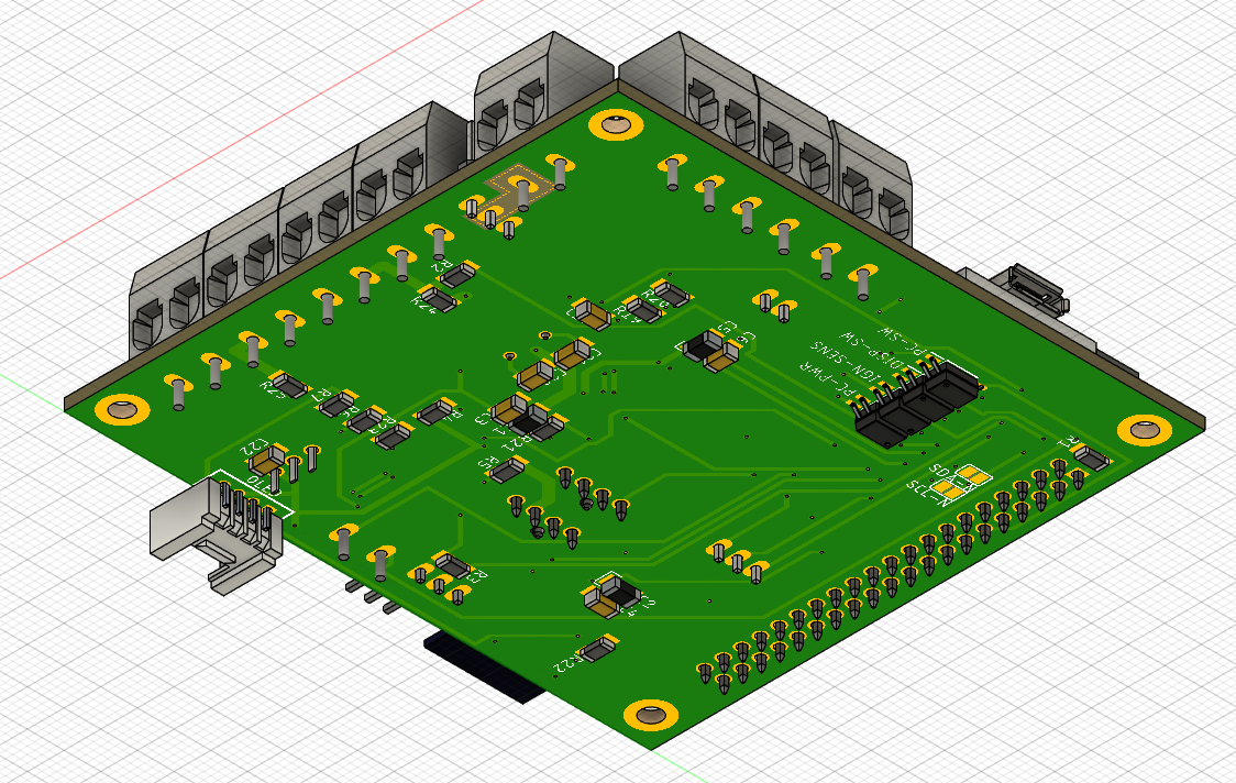
- Custom board design to incoorporate MCU, Bluetooth and Canbus logic on the same board
- iDrive 7-Button Controller
- DS18B20 Temperature Probe
- LTC3780 Power Supply Module
Purpose
This project is intended to support an Odroid N2 in its function as a car-pc. This also involves controlling the display brightness of the Vu7+ display by applying PWM signals to its backlight chip by reacting on the cars' light sensor on the windscreen. As a bonus it's designed to support an iDrive controller as an input device for the Odroid to have comfortable access to the car-pc functions. To make it function properly an app called "Button Mapper" is used to react on F-Keys. See: https://play.google.com/store/apps/details?id=flar2.homebutton
Electrical Details
The brainbox of this module is a Arduino Nano 33 IoT which has its own 3v3 voltage regulator on board. To reduce stress it is supplied by the onboard 5V regulator from Recom. This 5V supply also powers the TJA1050 controller which needs 5V in order to generate the signals on the CAN-Bus. The Bluetooth module, MCP2515 and INA219 are supplied by the Arduino's voltage regulator.
The 5V Regulator is supplied by an external power supply and tolerates a maximum of 12V.
Because of the internal wiring of the Arduino, even the Fans will work when the Arduino is powered via USB. You will read 3V on the 12V rail if only the Arduino is plugged in to a Supply via USB. I've missed to include a Schottky Diode in order to prevent this behavior but it doesn't hurt either because everything is on the same potential and the internal regulator of the Arduino can deliver 1A continously. This also enables you to diagnose things on desk without hooking up everything to a external DC supply.
Part selection
When selecting parts I've focused to select hose which are either AECQ100 certified or have an extended operating temperature range until at least 85°C. You should select parts for automotive use to ensure they last as long as possible.
- ATTENTION: Contrary to the schematics and board, the TCMT1100 up to TCMT1102 optocouplers can be used.
The TCMT1104 requires 10mA to trigger which the SAMD21 can't deliver. It's maximum current on a pin is 7mA
Fan sockets
The PWM signal is tuned to work with all fans. I've tested bog standard 120mm fans as well as a dual high-pressure cisco switch fan. Please note that the socket delivers the voltage from the 12V rail. There is no possibility to power 5V fans here.
3rd Party Libraries used
I'm using a modified version of the BPLib that now supports sending and holding multiple keys. That's probably important for future tweaks. The original library only supports sending one single key and modifiers. See: https://github.com/Neuroquila-n8fall/BPLib
Also: Seeedstudios Canbus Shield library See: https://github.com/Seeed-Studio/CAN_BUS_Shield
Usage
Intended Usage & prerequisites
The main key aspect of the layout is to connect an external power supply which is supplied by the battery of the car through the board. The intention behind this is to keep everything safely connected. Cars are very flammable and therefore the top priority has to be that there is no risk of loose, uninsulated wires dangling around!
A DS18B20 temperature probe is required in order to keep track of the temperatures of the pc and control the fans accordingly.
Wiring
This new revision has everything on board which makes wiring very easy. It also minimizes the amount of wiring.
 All of the terminals have a Description on the bottom which usually is hidden by the terminal itself. That's why a more descriptive text is added to the top.
You'll find a Terminal for the following auxillary devices:
All of the terminals have a Description on the bottom which usually is hidden by the terminal itself. That's why a more descriptive text is added to the top.
You'll find a Terminal for the following auxillary devices:
- Display (VU7A+): One Output for controlling the background lighting and one for triggering the power button
- CAN-Bus: You can hook up your K-Can to the screw terminal or the pin headers behind.
- PC: This is the output for the Odroid. It receives power directly from the 12V terminal
- 12V: Power supply input from an external regulated power supply. I heavily recommend a supply board with the LTC3780 chip.
- IGN: Ignition. Two terminals are available because we only need one positive input. In case you want to hook up something on the ignition, this is the right place
- IGN-AP: Ignition output for Access Points. I'm using the Teltonika RUT850 which needs this supply in order to power up and down on itself
- BAT: Battery Input. Used by the control logic to check for voltage levels and also delivers power to the DC Supply
- PSU (BOUT): Battery Out. Intended to be used as Output to the power supply. This Terminal is switched by the "1/0" pin header between"IGN-AP2 and "BAT"
- BAT-AP: Used by the Teltonika access point as permanent supply
Color blocks explained
- Green: Shared 12v Rail
- Orange/Yellow: Shared Ignition Rail
- Purple: Shared Battery Rail
Parameters
Parameters are described inside the source file "main.h" (https://github.com/Neuroquila-n8fall/odroid-carpc-nano33/blob/master/src/main.h) Everything is well tested and works right out of the box. The prototype is already reaching one year of service on my car and shares the same code base.
I2C
There are two solder pads "SCL-N" and "SDA-N" on the bottom to be bridged when you want to establish I2C communication between the Odroid N2 and the Arduino. This will join the N2 to the Arduino I2C bus. Important: The Arduino is the bus master!
First-Run
Bluetooth Module Setup
Before uploading the sketch to the Arduino, you should head over to the setup section and uncomment the line "initalSetup()". Then, head over to the function and customize the name of the device and PIN. This will then set the required settings on the next startup of the Arduino on the bluetooth module so it works as intended. You may also use a Serial redirection sketch to enter the commands yourself or tweak things. After that you should comment the section again and re-upload the sketch.
Functions & Behaviour
Startup
When you open the car by keyfob, the PC will be started by pulling down the power button GPIO pin on the Odroid for a second. This will turn on the Odroid.
Shutdown
When you close the car by keyfob, it will pull down the GPIO pin again but now for several seconds which triggers the shutdown routine of the Odroid so it shuts down gracefully.
Queuing
You can queue exactly one action by pressing "open" or "close" on the keyfob respectively.
What does this mean?
This means that if you want to take something out of the car and leave it again, you will have to press "open" and "close" in a rather short timespan. usually this would mean the startup process will be terminated or the PC will run until you enter the car again or press the "close" button again after the Pc booted up. Instead the controller stores the second action and waits for the PC to boot up and then shuts it down gracefully again. Because we never now when a "open" is followed by driving or just for accessing the car for a short duration this system prevents ungraceful shutdowns or battery drain.
Vice-Versa this means when closing the car and re-opening it again, the Odroid will be started again shortly.
Battery Monitoring (WIP)
- If the battery drops below a certain voltage, the Odroid will be shut down gracefully
- Fans will be shut down
- Everything else stays active. I'm planning to save energy by only enabling WiFi if the ignition is on.
WiFi
- Wifi is included and active and intended to provide IoT functionality in the future. I have yet to think about useful scenarios where this feature comes in handy
- As of now WiFi is used to synchronize the RTC via NTP
iDrive Controls
If an iDrive Controller is placed on the CAN Network, the controller will start to communicate with the network. The Sketch has the correct facilities in place to keep it awake and enable the rotation encoder. I've tried to resemble the original behavior of the iDrive controller.
- Rotation is scrolling up and down respectively
- Pushing the Menu button or the knob equals "Enter"
- Pushing the knob in any direction will emulate a directional arrow key so you can navigate in two dimensions between UI elements.
Things worthy of noting:
- Some apps don't come with keyboard support. Android is a touch-centric OS and therefore only a few devs implement full fledged keyboard control. Apps that work well are: Sygic, Spotify, Torque, Google Maps, Chrome
- You should use the button mapper app to implement extended features like return to home by long press and stuff like that
- Mapping buttons to apps can be done via Odroid Settings
Multi Function Steering Wheel Buttons
Native support is integrated which means you can skip music tracks with the arrow keys and fast-forward and rewind when holding those buttons.
Display Brightness Adjustment
The controller fetches messages from the CAN network from the RLS module (Regen Licht Sensorik) which sits, if fitted, on the windscreen behind the rearview mirror. It then maps those values to control the screen brightness of the VU7a display. The control values are proven but may vary between cars.
Signalling & Diagnosis
There are plenty of status led on the board:
- One for the battery rail which indicates that the battery is connected
- One for the 12v rail to indicate a working power supply input
- One for the ignition rail so you know if the ignition input works
- One for the 3v3 and 5v rails
- 2 for the bluetooth module: BTACT = Activity: Tells you what the module is doing, BTSTA = Status: Off when a device is connected
- 2 for the Arduino: STA tells you if the PC is running, ACT tells you if there is activity on the CAN-Bus and pulses when nothing is going on
- One for the fans: On if the relay is opened and fans are enabled
- There is also an optional OLED Grove connector. Because of timing issues I removed it from the project but it can be used as a diagnostical device if needed. Since 5v and I2C is supplied there, you can hook up other stuff to this port.
Known Issues
As soon as the car battery is depleted, the arduino will write value 0 to the display brightness pin when the engine starts or doors are fully opened and closed. I have yet to understand why on earth this is happening even when the engine is already running. I can only think of a solution where the brightness is updated frequently, like 10 seconds or so.
Solved: Explicit correction of values that are out of range. When the car has recovered from a very low voltage level, the light sensor reports values that are not mapped correctly by the "map" function. Such values are now being overwritten
When the car is not shut and goes into hibernation and the car pc is still running, it might happen that the display goes dark. This might also be related to the aforementioned problem and may point to an integer overflow issue on the brightness calculation. Maybe the sensor on the windshield (RLS Control Module) sends some crazy data when it goes into hibernation.
Solved: Same issue and solution as above
-
Sometimes the "restart" feature of the queuing mechanism doesn't work. Odroid will then start after the ignition is on.
-
Apparently setting the PWM clock to 25kHz in order to control PWM fans also affects the display brightness pin somehow. This is something I didn't see coming. Maybe another pin configuration is needed...
Questions I got asked...
Why all the hassle if I could just simply upgrade the car to the official iDrive? Because I always felt the need to include a full blown car pc into my car. Upgrading to iDrive wasn't an option due to the fact that this system is just too limited. If I had a recent model, this wouldn't be a problem but sitting on a rather "old" car leaves one without options. I want a browsable music library with cloud sync, internet, the precious Torque app, ...all the good stuff! The icing on the cake was the decision to go the extra mile and swap the center console and install an iDrive 7-Button control unit. It looks like OEM but it does much, much more.