Open Smitty-44 opened 3 years ago
Hi,
OpenCR for OP3 requires a special firmware that communicates between PC and DYNAMIXEL. This firmware can be uploaded from Arduino IDE. Install OpenCR Board manager in Arduino IDE and upload OpenCR > OP3 > opencr_op3 sketch. Please note that OpenCR does not support Arduino IDE on Raspberry Pi, so use PC or laptop to upload the firmware.
The OpenCR USB port for Raspberry Pi is configured as below in TurtleBot3.
Copy 99-turtlebot3-cdc.rules file into /etc/udev/rules.d/
directory.
Then run below commands.
$ sudo udevadm control --reload-rules
$ sudo udevadm trigger
For setting up the Raspberry Pi hotspot, you'll need to search for Raspberry Pi forum as we do not provide tech support on a third party products.
If you are planning to add a camera, Raspberry Pi 4 may not be a feasible solution as vision processing requires quite a lot of processing power and OP3 is designed for processing without an external PC. In that case, you might want to try something like NVidia Jetson Nano, but take my word with a grain of salt as I don't have complete understanding on your project. Thank you.
Will Son, thank you so much for your quick reply. I had already done the first section of uploading the opencr_op3 sketch.
I just performed the second section with copying the 99-turtlebot3-cdc.rules file and running those specified commands.
Still the exact same result when issuing: $ roslaunch op3_bringup op3_bringup.launch.
I will go ahead and look for a Raspberry Pi forum for the hotspot direction. At this moment I do not have a camera, just an rplidar.
Thanks again for your quick response, Jay
Hi Jay,
Did you connect the U2D2 to the Raspberry Pi?
OP3 uses U2D2 to communicate with DYNAMIXEL while OpenCR provides power and IMU data.
Since your RPLIDAR is connected to ttyUSB0, you'll need to modify the op3_manager.launch
in the op3_manager package so that correct port name is assigned to the U2D2 (by default, ttyUSB0 is assigned in the launch file).
Thanks.
Hi Will Son, I didn't connect a U2D2 to the Raspberry Pi. I do have one though. So, the next question is, what is the precise physical hookup? My dynamixels are TTL. Do I connect the U2D2 directly to the Pi with a short USB cable, then use a 3 pin cable (TTL) to connect the U2D2 to the OpenCR? I tried that setup, but no ttyACM0 showed up at all. I had changed the ttyUSB0 to ttyACM0 from the beginning. Do I need a UART cable to connect the U2D2 to the OpenCR? Thanks for your help, Jay
On Sun, Dec 6, 2020 at 7:40 PM Will Son notifications@github.com wrote:
Hi Jay, Did you connect the U2D2 to the Raspberry Pi? OP3 uses U2D2 to communicate with DYNAMIXEL while OpenCR provides power and IMU data. Since your RPLIDAR is connected to ttyUSB0, you'll need to modify the op3_manager.launch in the op3_manager package so that correct port name is assigned to the U2D2 (by default, ttyUSB0 is assigned in the launch file). Thanks.
— You are receiving this because you authored the thread. Reply to this email directly, view it on GitHub https://github.com/ROBOTIS-GIT/ROBOTIS-OP3/issues/105#issuecomment-739598786, or unsubscribe https://github.com/notifications/unsubscribe-auth/ANVLKU7GRMTH22QK6XA453TSTQP77ANCNFSM4UKV7BSA .
Hi Jay, The proper hardware configuration can be found from the OP3 eManual. U2D2 will be using ttyUSB0 port while OpenCR will be assigned to ttyACM0 on RPi.
Hi Will Son, Ok, so after a host of different setups and small changes here and there to try and understand what is happening...or not happening... I had the OpenCR connected directly to my Desktop PC, using arduino IDE, I was able to test and move each dynamixel. When I turned on the power to the OpenCR, the leds on all the motors flashed. I was able to move 2 of them at the same time as well. I have defined them 1 thru 26 at a baudrate of 2M. The first 20 match exactly with the 20 for the OP3. I am using XM430-W210s, XL430-W250s, and a few 2XL430-250. Then, I compiled and uploaded the opencr_op3 sketch to the OpenCR. So, far so good.
I connected my U2D2 to the Pi (USB cable) and then the U2D2 to the OpenCR board (TTL cable 3pin). The power is still attached to the OpenCR board as before. Now, when I turn on the power, the leds on the dynamixels do not flash, but, everything else starts up. The Pi starts up, OpenCR board, too. I have a Pi power cable connected exactly as on the turtlebot3. I try to roslaunch the op3_manager rx1_manager.launch...I am using /dev/ttyUSB0 as instructed. The software seems to be doing its thing, and the messages on the screen show manager-init, Torque on DXLs!, it goes through the list of dynamixels with their IDs and USB0, etc. And then I get the same type of errors (JOINT[...] does NOT respond!!) as from this thread on your github OP3 issues:
https://github.com/ROBOTIS-GIT/ROBOTIS-OP3/issues/50#issuecomment-415257202
So, it seems it's a power issue, but only after uploading the <opencr_op3 sketch> to OpenCR. In problem #50, a solution was never posted...except what appears to be from you:
https://github.com/ROBOTIS-GIT/ROBOTIS-OP3/issues/50#issuecomment-703384341
But, I'm not understanding what you are saying. I am using both the U2D2 and the OpenCR. And right now the power cord is connected directly on the OpenCR.
I enclosed a pic setup.
Thank you for all your help, Jay
On Tue, Dec 8, 2020 at 9:21 PM Will Son notifications@github.com wrote:
Hi Jay, The proper hardware configuration can be found from the OP3 eManual https://emanual.robotis.com/docs/en/platform/op3/quick_start/#system-block-diagram . U2D2 will be using ttyUSB0 port while OpenCR will be assigned to ttyACM0 on RPi.
— You are receiving this because you authored the thread. Reply to this email directly, view it on GitHub https://github.com/ROBOTIS-GIT/ROBOTIS-OP3/issues/105#issuecomment-741470926, or unsubscribe https://github.com/notifications/unsubscribe-auth/ANVLKU65GTORZRN4VK4OGQDST3NIXANCNFSM4UKV7BSA .
The DYNAMIXEL power line of the OpenCR is controlled with an FET which is electronically controlled with a digital signal from MCU. In order to turn on this FET and supply power to DYNAMIXEL, OpenCR should be properly connected to the controller(Intel NUC in case of OP3), and once the connection is properly made, the op3_manager will try to turn on this FET as shown in the code below. https://github.com/ROBOTIS-GIT/ROBOTIS-OP3/blob/master/op3_manager/src/op3_manager.cpp#L183
Hi Will Son, I want to start by saying thank you again for your help and your quick replies. I got through the bringup process successfully and successfully added my lidar launch to the bringup file. I want to let you know the dynamixels never flashed, but the torque was turned on, and the motors held their ground. So, there must be power getting through, not just the signals. My next error, which I expected, is the op3_manager process dying and giving an exit code -11. I am speculating that might be related to the hotspot not being added to my Pi setup yet. So, I have joined the raspberry pi website and began asking questions over there. I will continue to plug away. Thanks again, Jay
On Thu, Dec 10, 2020 at 7:33 PM Will Son notifications@github.com wrote:
The DYNAMIXEL power line of the OpenCR is controlled with an FET which is electronically controlled with a digital signal from MCU. In order to turn on this FET and supply power to DYNAMIXEL, OpenCR should be properly connected to the controller(Intel NUC in case of OP3), and once the connection is properly made, the op3_manager will try to turn on this FET as shown in the code below.
https://github.com/ROBOTIS-GIT/ROBOTIS-OP3/blob/master/op3_manager/src/op3_manager.cpp#L183
— You are receiving this because you authored the thread. Reply to this email directly, view it on GitHub https://github.com/ROBOTIS-GIT/ROBOTIS-OP3/issues/105#issuecomment-742888297, or unsubscribe https://github.com/notifications/unsubscribe-auth/ANVLKU6IEJDJJTR2PVLWCVLSUFSDZANCNFSM4UKV7BSA .
Hi Jay, Thank you for the updates and glad that all DYNAMIXEL are getting powered. Every DYNAMIXEL should blink once when powered, and if you didn't see them blinking, there must be something wrong. The DYNAMIXEL will be powered while launching the op3_manager. Keep it up and wish the best for you!
Hi Will Son, It's me again. Well, I took a look at this: https://user-images.githubusercontent.com/60127681/80435326-267aa580-8937-11ea-810e-117670705446.png And I saw RS485...and I'm using TTL (XM430-W210-T)...is using TTL just not going to work OR is there another possible setup using TTLs? My setup is very similar but using the 3pins instead of the 4pin, including hubs and U2D2, too.
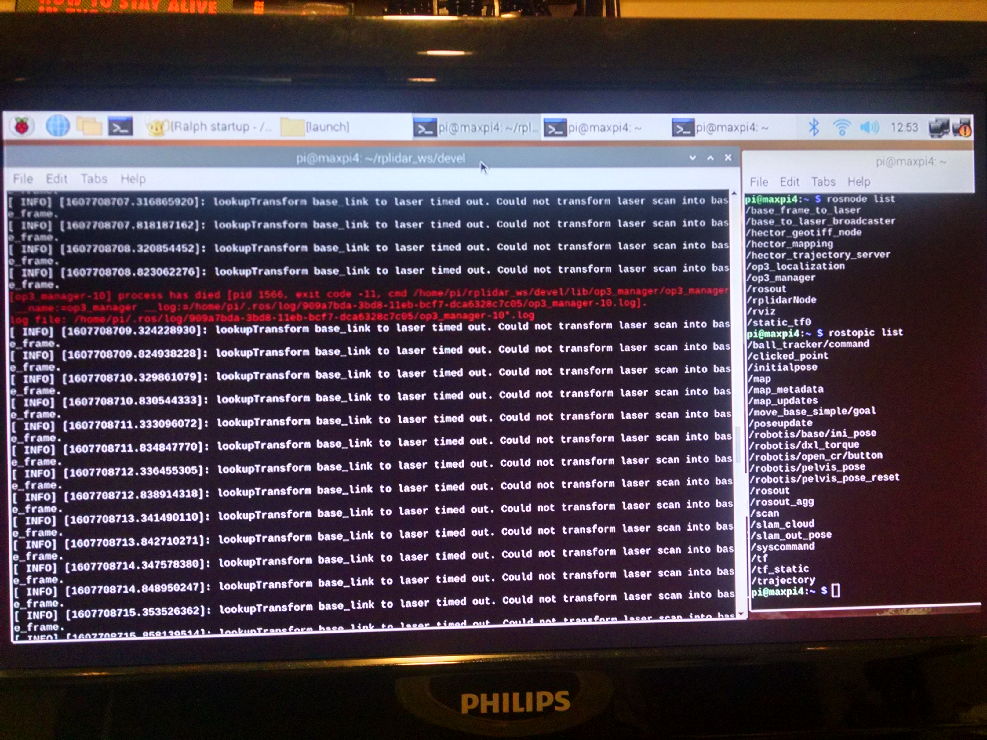
When I roslaunch op3_bringup, it actually seems to startup fine...and I have added the rplidar launch code to it as well. The lidar spins and rviz opens up and that all works fine so far. I get the manager-> init and the Torque onDXLs! It displays the OP3.robot contents. All that looks good. When I look at the U2D2 (all different LED colors are blinking) and the OpenCR (user leds), they are both flashing as if they are communicating. Then the op3_manager process has died. exit code -11. It says look in the op3_manager-#*.log, but when I look, it isn't there. (# keeps changing of course.) [image: op3managerError.jpg]
Anyway, back to my original question, by using TTL for the dynamixels, is that a problem? I have some work to do on RVIZ and the transforms, etc, but that's for another day, down the road.
Also, I have roslaunched op3_demo self_test.launch, as well, with its many rosnodes and rostopics. And the voice speaks, "self test ready mode".
So, there you have it. Maybe my power problem has been the TTL all this time. Thanks as always for your help, Jay
On Sun, Dec 13, 2020 at 9:00 PM Will Son notifications@github.com wrote:
Hi Jay, Thank you for the updates and glad that all DYNAMIXEL are getting powered. Every DYNAMIXEL should blink once when powered, and if you didn't see them blinking, there must be something wrong. The DYNAMIXEL will be powered while launching the op3_manager. Keep it up and wish the best for you!
— You are receiving this because you authored the thread. Reply to this email directly, view it on GitHub https://github.com/ROBOTIS-GIT/ROBOTIS-OP3/issues/105#issuecomment-744119962, or unsubscribe https://github.com/notifications/unsubscribe-auth/ANVLKUZTQSBYI6K4T7JHSXTSUVWVRANCNFSM4UKV7BSA .
Hi, @Smitty-44 RS-485 DYNAMIXEL can be replaced with TTL DYNAMIXEL without any modification in the code as long as you are sticking to one communication type. Looks like your scan from the rplidar cannot be transformed. Make sure you have correctly modified the URDF and tf tree shows the connection properly. These modifications, unfortunately can not be supported from our side as it exceeds the boundary of our technical support for the official platform. I'd recommend to use ROS2 Answers forum where many experienced developers hang out and you may find similar cases. Thank you.
Hi Will Son, I hope you had a great holiday season. I took some time off from this. I came back with a clearer head and almost made it through the bringup process.
All the messages printed out as a successful bringup...except I had a voltage drop...and the opencr/dynamixels lost power for about 3 seconds. Then they came back on, and the leds on the dynamixels flashed but no torque. I launched the op3_gui_demo and I was able to click and choose options and messages were being sent and received but no movement.
I see there was an issue for the OP3 concerning a voltage drop. I am wondering if that is indeed my problem. If so, I would need to rewire the dynamixels a certain way. I do not understand the reasons why the OP3 dynamixels are wired their specific way to overcome the voltage drop problem. Can you explain the logic behind the specific reasoning of separating the two legs and why that causes it to work? I have 26 joints: the first 20 exactly as OP3, but 2 additional for each arm, and 2 right above the hips (lower torso; pitch and yaw).
My wiring is as follows; U2D2 connected to opencr, left leg and the two torso dynamixels connected directly to opencr, and all the others (18 total) joined to a hub and then connected directly to opencr.
I looked at this: voltage drop https://github.com/ROBOTIS-GIT/ROBOTIS-OP3/issues/94#issuecomment-628400002
Thanks again as always, Jay
On Sun, Dec 20, 2020 at 8:57 PM Will Son notifications@github.com wrote:
Hi, @Smitty-44 https://github.com/Smitty-44 RS-485 DYNAMIXEL can be replaced with TTL DYNAMIXEL without any modification in the code as long as you are sticking to one communication type. Looks like your scan from the rplidar cannot be transformed. Make sure you have correctly modified the URDF and tf tree shows the connection properly. These modifications, unfortunately can not be supported from our side as it exceeds the boundary of our technical support for the official platform. I'd recommend to use ROS2 Answers forum https://answers.ros.org/questions/ where many experienced developers hang out and you may find similar cases. Thank you.
— You are receiving this because you were mentioned. Reply to this email directly, view it on GitHub https://github.com/ROBOTIS-GIT/ROBOTIS-OP3/issues/105#issuecomment-748714920, or unsubscribe https://github.com/notifications/unsubscribe-auth/ANVLKU2DKCMDFBDGW6COYCDSV2TRVANCNFSM4UKV7BSA .
Hi Jay,
I hope you too had a great holiday and beginning of the new year!
OP3 is designed with OpenCR to provide sufficient power for operation. If you are having a voltage drop issue, please check if your electrical system can provide sufficient power. When connecting multiple DYNAMIXELs, it is recommended to directly connect to the power source, but please be aware of the operating voltage of DYNAMIXEL. Depending on your robot design, you should also revise the electrical configuration based on your requirement so that voltage drop would not occur.
Thank you.
Hi Will Son, So, I'm using the 12V power supply from Robotis connected to the OpenCR board. [image: temp_3.jpg]
And I'm using the U2D2, which is connected directly to the OpenCR board. All the dynamixels are coming in and connected to the OpenCR board as well. My configuration is almost identical to this:
[image: issues94.png] except, mine are TTL, not RS485, AND I have 26 joints instead of 20. (2 more on each arm, 2 more at the waist) While launching the bringup file: [image: temp_2.jpg] and... [image: temp.jpg] So, when the robot is moving to initial pose, power drops out for the OpenCR board for about 3 seconds as shown in the attached short video (temp_7.3gp). (18 seconds)
You can see in the video, the green light on the OpenCR goes out, then back
on, and then the leds blink on the dynamixels.
So, the
I feel like I couldn't be any closer to all of this working. The Pi has its own power supply, so it doesn't have an issue. The rplidar is connected to the Pi as well.
Thanks again, Jay
On Tue, Jan 26, 2021 at 3:12 AM Will Son notifications@github.com wrote:
Hi Jay,
I hope you too had a great holiday and beginning of the new year!
OP3 is designed with OpenCR to provide sufficient power for operation. If you are having a voltage drop issue, please check if your electrical system can provide sufficient power. When connecting multiple DYNAMIXELs, it is recommended to directly connect to the power source, but please be aware of the operating voltage of DYNAMIXEL. Depending on your robot design, you should also revise the electrical configuration based on your requirement so that voltage drop would not occur.
Thank you.
— You are receiving this because you were mentioned. Reply to this email directly, view it on GitHub https://github.com/ROBOTIS-GIT/ROBOTIS-OP3/issues/105#issuecomment-767376862, or unsubscribe https://github.com/notifications/unsubscribe-auth/ANVLKU6X3F22WAYSR652DMTS3Z2PPANCNFSM4UKV7BSA .
Jay,
It seems like pictures and video are not properly attached in the thread. The ROBOTIS 12V SMPS is limited to 5A supply and connecting 26 DYNAMIXEL may need much more juice than that. Also please note that the SMPS barrel jack is somewhat inconsistently contacting to the connector while the robot is moving, so it is recommended to connect the LiPo battery to OpenCR even if SMPS is providing power to the robot.
The best option will be supplying power directly from 11.1V LiPo battery so that you don't have to worry about voltage drop. I'm still unsure what exactly causes the OpenCR reset, but I'm suspecting the power source.
Please generously understand that I cannot thoroughly review on your personal project based on our OP3 unless the technical support on customer's project is officially requested via contactus2@robotis.com.
Thank you.
Hi Will Son, Sorry for the late reply. No problem with any of what you say. Connecting the battery did indeed stop the voltage drop.
I wanted to let you know I was able to startup the robot using the bringup launch file. Also, I was able to use the tuner launch file as well to tweak the joints/offset. It is still a work in progress, but it works, and is what I needed to get going. Now, I can proceed further and start working on motions and clean up the lidar. I really appreciate all of your help.
Thank you again and cheers! Jay
On Wed, Jan 27, 2021 at 12:14 AM Will Son notifications@github.com wrote:
Jay,
It seems like pictures and video are not properly attached in the thread. The ROBOTIS 12V SMPS is limited to 5A supply and connecting 26 DYNAMIXEL may need much more juice than that. Also please note that the SMPS barrel jack is somewhat inconsistently contacting to the connector while the robot is moving, so it is recommended to connect the LiPo battery to OpenCR even if SMPS is providing power to the robot.
The best option will be supplying power directly from 11.1V LiPo battery so that you don't have to worry about voltage drop. I'm still unsure what exactly causes the OpenCR reset, but I'm suspecting the power source.
Please generously understand that I cannot thoroughly review on your personal project based on our OP3 unless the technical support on customer's project is officially requested via contactus2@robotis.com.
Thank you.
— You are receiving this because you were mentioned. Reply to this email directly, view it on GitHub https://github.com/ROBOTIS-GIT/ROBOTIS-OP3/issues/105#issuecomment-768036279, or unsubscribe https://github.com/notifications/unsubscribe-auth/ANVLKUZQ2QUQI5AVSI52BZDS36OMDANCNFSM4UKV7BSA .
Jay,
Appreciate your understandings and updates on your project progress. As you are developing a OP3 like humanoid, marketing team may also have an interest in your project. If you are posting your project on a specific channel, we are happy to help spreading the words for your project :) Happy developing and stay safe!
The RPI 4 is great for OP2 and I assume OP3 as well. No problems with processing power, I can have a live feed from the camera and display all my visual diagnostics created with opencv and only use 30% CPU.
The NUC weighs far too much for such a small biped, a CM740 and the Pi is the way to go.
https://www.youtube.com/watch?v=40ikFDVgt7s&t=91s
M
@bryntirion2 Thanks for the udpates. You're right, the NUC is getting heavier for a small sized humanoid and SBC could be a good substitute for it. Are you running the robot on ROS1 Kinetic?
Japanese ROBOTIS competitor (non-Dynamixel Humanoid) is RasPi4 + ROS 1 Melodic. They looks closed source. They don't seem to have a Github organization or repository. For reference. https://youtu.be/ayo-KIgPp14
@ROBOTIS-Shibata Here's another example of running humanoid with RPi + ROS. The ROS code has not been shared though. https://www.youtube.com/watch?v=57VoKIGZx9w
I am creating my own biped (26 DOF) which in many ways is similar to the OP3.
But, I have a Pi4 instead of a NUC. And I have a rplidar.
The Pi4 has Raspian installed and ROS melodic.
I have the Pi4 directly connected (usb) to a OpenCR.
I downloaded the OP3 code to the Pi4 workspace, and catkin_make just fine.
Using my windows desktop, I compiled, and successfully uploaded the OP3 code for the OpenCR.
I changed a number of modules/files (op3_bringup.launch, op3_manager.launch, offset.yaml, OP3.robot, dxl_init_OP3.yaml, etc.).
To simplify things, the first 20 motors of my biped match the location and name of the OP3 motors.
In this way, I only needed to add the extra 6.
I am using XM430-210-T(s) in the legs and torso, and XL430-250-T(s) for the arms). Baud rates set at 2M. I am using the 12V power supply and I know the dynamixels are getting power due to the leds flashing once.
In a Pi terminal, I type in (fyi, I'm using ttyUSB0 for the rplidar which works fine): $ export OPENCR_MODEL=OP3 $ OPENCR_PORT=/dev/ttyACM0 $ sudo chmod 666 /dev/ttyACM0 During roslaunch op3_bringup, it is apparent the Pi4 and OpenCR are not communicating as planned. I'm getting the errors as described here: https://github.com/ROBOTIS-GIT/ROBOTIS-OP3/issues/50
[ERROR] [1532100652.759606870]: Torque on DXLs! [[RxPacketError] Unknown error code!] [ERROR] [1532100652.895751751]: Fail to control LED [[RxPacketError] Unknown error code!] ...and... [ERROR] [1532100655.314481806]: [RobotisController] first bulk read fail!! terminate called after throwing an instance of 'boost::exception_detail::clone_impl'
How would I setup the WiFi Hotspot on a Pi4? emanual.robotis.com/docs/en/platform/op3/recovery/#pc-setting
Would any of the setup procedures or software for turtlebot3 help in this matter?
I didn't try any of that up to this moment due to mixing and matching those two software. I didn't want to create a much worse problem and maybe having to start over. As a sidenote, I am able to SSH into the Pi4 from my windows desktop so I can control from there and also use SLAM for the lidar. Any help or direction would be appreciated. Thank you very much in advance, Jay