Ralim / IronOS

Open Source Soldering Iron firmware
https://ralim.github.io/IronOS/
GNU General Public License v3.0
7.28k stars 723 forks source link

USB-C? #24

Closed daling closed 1 year ago

daling commented 7 years ago

Hey, a few weeks ago I got a pretty awesome idea: would it be possible to hack this iron into having USB-C PD input?

The USB-C specs allows for 3A at 20V, or even 5A. This would mean that it would be able to power the iron from like any common available charger. Sadly I don't have the knowledge nor the skills to pull this off .

Wouldn't that be pretty awesome? :D

I did some research and fount out that the STM32F0 devices can be used for USB-C PD. The STM32 in this TS100 is a STM32F1 and seems currently not supported. But my knowledge about STM32's and USB PD is very limited, maybe someone out there is able to tell us more.

whitehoose commented 5 years ago

Jenny Not saying you don't, As I said I have a 80 not a 100 but as I understand it the 100 doesn't require a negotiating supply - just lots of magic pixies. The "more sophisticated" ts80 works to qc3 which does require a supply capable of negotiating voltages. As many of us found not every QC3 power bank or PSU works with the 80 - so any info backed by real hands on experience is of interest.

As far as I knew 9v was the max - ralim seems to be hinting that 12v is possible - although my typical use of the 80 has never found it lacking so long as 9v is available.

My main point was that some people seem to be under the impression that it's all a matter of personal preference and that the electrical values all work independently or are largely governed my software not physics. This leads some to expect woefully underrated gadgets to supply massive amounts of power.

Without an intermediary converter or dual standard device QC can't talk to PD so it's not an option. On stock firmware the ts80 gives an error if plugged into a dumb usb2 powerbank because it needs that extra voltage boost to fire up. Anyone with any info on any device that adds versatility is of interest - but it has to be real world hands on use - not "afaik guesses" I know someone here has added a QC controller to a ts100. I'm not familiar with the 100 so can't really add anything to that topic - However it's an interesting option. So when you mentioned a PD device I was hoping you may have some hard experience too - disappointing that you haven't.

majuss for my money the all round handiest USB measuring device would be the rui deng UM34c, a good all-rounder for £15ish,

slightly cheaper is The USB Safety tester j7-t (£4 or £5) - both support qc2 & 3 AVO +power and mAh with graphing and battery charging/ capacity measurement for powerbanks etc . failing that you can get a bog standard usb avo for £2 If you already have a meter you could build a USB test rig for the cost of the solder and a few inches of wire
polarathene commented 5 years ago

@whitehoose I don't know how the TS80 works with QC3. AFAIK, QC3 is compatible with a variety of voltages for negotiating, but retains a maximum of 18W, so it doesn't really matter what voltage is negotiated for so long as it can pull enough amps/watts to get what it wants. If you get 9V/2A, that's 18W, if you get 12V/1.5A, that's again 18W. If the power source can deliver 12V at 1.5A, QC3 probably negotiates for that,otherwise it tries the next lowest voltage and amperage for trying to meet it's requirements to run. You will only get 5A over a cable if the cable and protocol support it(along with the power source), anything above 3A, tends to be at 20V afaik(at least with USB-PD).

Regarding the TS100, it is not clear. I assume it allows you to increase the heat manually if enough power is available? Or does it heat based on the power input? It takes any voltage between 12-24 via DC5525 jack, there's no negotiation stage there it's just power, no protocol. As mentioned earlier the product page I saw paired a wattage column beside the voltage one. Which gave a range of ~1.4 to ~2.7A to achieve the wattage with the given voltage. A user mentions here that they have used a 19V 6.5A PSU(~120W), but the heat up time was pretty much the same as 65W achieves, so going any higher than 65W probably has no benefit.

The TS80 on this product page shows the various QC3 inputs for power which are all ~18W or less with a varying voltage but fixed amperage for each range. The product itself states 9V/2A by the connector(based on the image there), so it probably prefers/expects that?

This issue/repo is for the ts100, where the topic of powering it with portable power source makes more sense than discussing ts80. Powering the ts100 via a power bank is less obvious/straightforward as you need a DC barrel connector and most power banks omit DC out(or have a fixed output voltage/amperage), so this topic is more about leveraging protocol/tech like USB-PD to draw more power from a compatible power bank to a device/cable that negotiates that and then outputs via DC5525 barrel plug. I don't own a soldering iron, but have been wanting similar functionality for powering a small computer(ODROID-N2) with similar issue.


@majuss I haven't done such myself, people often use multimeters, or there are some some small devices(at least for USB input/output) that can do this as well. Stuff like this one from Plugable, there are quite a few on amazon/aliexpress but quality varies, also need to make sure they support the fast-charge protocol like QC3 or USB-PD, or just passthrough, along with the voltage/amperage that you're interested in(QC3 at 9V would not be higher than 2A afaik).

I am still surprised that you're pulling more than 5V from the Macbook USB 2 port, I wouldn't expect that to work or be a good idea tbh.

whitehoose commented 5 years ago

@polarathene ALL powerbanks are DC out - the shape of the connector doesn't dictate the shape of the output. I have adapters to convert most common outputs to fit most common inputs to plugging a usb powerbank onto an XT60 is simple enough. The stopper (if there is one) is that the TS80 requires a QC3 compatible power source while the ts100 only requires the correct voltage source with a potential to deliver sufficient power.

With qc3 you always creep up on a value then stop. The whole point of all this is that irrespective of PD or QC - the device will initiate the negotiation for power the source controller will never "just" squirt out 20v@5A. In the same way with an iron YOU set the temperature and it's the iron's job to maintain your chosen level. If the power isn't available you won't attain the requested value - it's not a lottery you don't just plug it in and see - imagine the consequences if on a good(?) day your iron got up to 1000c or your radio started transmitting at 100KW.

All devices are built to a spec. In the case of PD that's mainly aimed at charging batteries or swapping power between gadgets some of those batteries are LiLon which are effectively a power black hole. You can pour masses of amps into them - so the 100w for PD is for charging a powerbank you can't pour those 100watts into a 1w LED and expect it to shine. You can have a psu with a potential to deliver - but (like a horse) you can't make the device drink it all.

Yes PD has a protocol and YES there is negotiation - it's known as "suck it and see" You start low and slowly up the game, but you have to be careful you don't exceed the capabilities of the device. So you can plug a PD into a device using a aaa cell - but whatever you do your 20v 100w device isn't going to work. In the case of USB. On power up all the basic services work by default at a the USB1/2 5v level - but in the case of the ts80 you can't power the tip (on stock firmware) however the iron can use qc3 to negotiate with the power source for more power - if the power source doesn't understand - it maintains 5v ... if you increase the voltage manually - I'm not certain what will happen.... the ts80 won't be in the correct state to deal with 9v ... whether it can switch, compensate or what I'm interested to know. (but not interested enough to try it!) ..... However because it's a closed loop the voltage increases to 9v. or possibly (depending on the device and bank) 12v, This isn't a maybe it's down to the spec of the device as well as the bank and needs a serious set of cells to deliver a meaningful power level @12v. I'd also expect a device that requires 12v to at least show some signs of life at 5 and 9v too.

Finally you can get a big lipo or similar - s4 or above and use a buck converter to limit what the battery is allowed to deliver to meet the spec.

In all cases you start safe (5v) and crawl through the options 20v@5A will simply fry an unprepared device 9v@5A will only consume 2a max (18w) (or your example <65w isn't not effective) it's because at that voltage the circuit won't ..... no - CAN'T convert the amps to power because that's not how PHYSICS works!!! back to the ts80 because the tip is 4.5v and Georg Simon Ohm (ohm's law) and James Prescott Joule decree that's what will happen (resistance trumps amps) BUT if something shorts - it's not going to end well ... so in general your ower meets te needs of te device - rarely the other way round.

With safety in mind you'd also want some form of fuse or other limitation.

In a powerbank you have 2 config options a single 3.8v or a bank of cell(s) connected in parallel (able to deliver high current, but only a fixed 3.8 voltage) and a boost converter that makes a the designated output voltage(s) as per spec with a consequential reduction in current. so a 2000mAh cell delivers 1500mAh The other way is a number of 3.8v cells connected in series (variable voltage 3.8, 7.2 etc , lower fixed max current) cell imbalance will have some effect - but under 20v it's not usually an issue

We now have a fixed resistance (4.5 ohm) and a variable voltage qc3 makes provision for 5-20v (20v=88.8w). That's physics. If we say watts are the ability to do work on a 4.5 ohm load 9v=18w, 12v=32w unless 18w is derived using devious means otherwise it requires a change in resistance (which in the ts80's tip isn't an option). you can see the relationships here http://www.sengpielaudio.com/calculator-ohm.htm.

There are various sources for studying electrical theory - perhaps a 101 course would clear up a few of the many misconceptions you hold. Literally - it's not rocket science.

polarathene commented 5 years ago

@whitehoose That's ridiculous... That's like claiming my VGA/DVI only displays support HDMI because I can use an HDMI adapter to use HDMI from my GPU. They're not able to utilize any of the added benefits from HDMI though are they.

Yes... there are cables that will have a USB male connector on one end and a DC barrel male connector on the other end. Those are either passively sending 5V and whatever amperage(100mA?) that is sent when there is no negotiation. There are ones with converters to up the voltage and they negotiate for however much amps(I don't know how this works, perhaps they can just pull amps instead of requesting in load units like USB spec requires), which could be up to 2.4A at 5V from my power bank(12W), but going to 9 or 12 volts reduces the amperage output from that adjustment as well as additional efficiency loss, so now I end up with less than 1A/10W.

Proper DC out, allows for a higher voltage without that additional loss, it should be able to output the maximum 15W that the powerbank allows for(12V/1.25A), those few extra watts make all the difference for my requirements. With a TS100, that's not going to be sufficient either way. A more capable powerbank with DC out capable of higher wattage could work, or a USB-PD capable powerbank could utilize an adapter like PD-Buddy Sink and output to a DC barrel connector that way. Someone shared a product earlier though which is a USB-C cable that is preset to negotiate 15V or 20V and has a DC5525 output connector, I guess for amps they're just pulled as needed up to the 5A ampacity of the cable.

The whole point of all this is that irrespective of PD or QC - the device will initiate the negotiation for power the source controller will never "just" squirt out 20v@5A.

If the power isn't available you won't attain the requested value - it's not a lottery you don't just plug it in and see

As I said, I don't own a TS100, I've never even used a soldering iron, I don't know how they are working with the variable voltage and amps. I can only assume it's similar to the DC powered product I have, which supports a range of voltage input and has power requirements in watts, with some on-board circuitry to adjust the voltage to the boards operational needs and then use whatever amps are available/supported.

You can provide a direct source to TS100 of 20V/5A and it'll work with that just fine, no QC or USB-PD involved. AFAIK, it wouldn't be happy if given 10V or 30V though.

If you control the temperature through some interface on the iron, and that raises the amps drawn accordingly to get whatever wattage it needs to reach that temperature, great.

so the 100w for PD is for charging a powerbank you can't pour those 100watts into a 1w LED and expect it to shine. You can have a psu with a potential to deliver - but (like a horse) you can't make the device drink it all.

The LED just needs to receive the correct voltage and be able to draw the amps it needs. Have I said something earlier that suggests that I don't understand what you're saying here? I've only seen the specs for the TS100 that state ranges of 17W to 65W, others here seem to think that it might be possible to go beyond that limit, I linked to a discussion which confirms 65W was the limit. You or someone else were wanting 12V on QC3, even though that wouldn't really make any notable difference in wattage afaik as the max amperage is adjusted accordingly to achieve the same max wattage as you'd get with 9V.

So you can plug a PD into a device using a aaa cell - but whatever you do your 20v 100w device isn't going to work.

I never claimed such did I? If something supports USB-PD, the negotiation itself should handle what can be achieved, the device requesting the power doesn't have to be careful here. If it wants 80W via 20V/4A, but the USB-C cable only supports 3A, it already knows this and won't be able to successfully negotiate. If it was a 5A capable cable, then the e-marker will have expressed that capability and provided the power source can meet the request, the negotiation is successful and power is delivered.

In all cases you start safe (5v) and crawl through the options 20v@5A will simply fry an unprepared device

Only if the device cannot work with 20V. A device only draws amps that it needs, it could be 200 amps made available and it'd only sip in the amps it wants at 20V, the cable providing the 200 amps though would need to have the appropriate ampacity otherwise hello fire. USB-PD and QC cannot draw 20V immediately, they are drawing via USB and need to negotiate first otherwise it's not safe to try pull what can't be supplied.

9v@5A will only consume 2a max (18w) (or your example <65w isn't not effective) it's because at that voltage the circuit won't ..... no - CAN'T convert the amps to power because that's not how PHYSICS works!!!

Sorry, what? 9V/5A is 45W. If the power source can provide that, and the device can work with it, there isn't a problem. I'm not that great on physics knowledge, so feel free to link me to something that says otherwise. You can find power supplies of 9V/5A though. QC3 limits 9V to 2A due to the max 18W QC3 supports. Another reason for the lower amperage(and perhaps your physics reasoning) is the ampacity of the cable, you don't want to push 5A through a 28AWG wire for example. The TS100 won't take it because it has a min voltage requirement of 12V, the TS80 won't take more than 2A at 9V because it's exceeding QC3 protocol.

We now have a fixed resistance (4.5 ohm) and a variable voltage qc3 makes provision for 5-20v (20v=88.8w). That's physics.

At 20V with QC3, you'd probably be getting 900mA to cap at 18W. The variable voltage is being handled at the power source(power bank in this case). I'm vaguely famliar with the internals of such products, but regardless of their internals, they output currents at specific volts and amps. Those vary based on what protocols are supported and requested.

unless 18w is derived using devious means otherwise it requires a change in resistance (which in the ts80's tip isn't an option).

The TS80 negotiates for 18W over QC3 presumably not caring what the current voltage/amps are, so long as they're within that supported range, and can be adjusted through some regulator on-board if needed? I don't know how soldering irons work with electricity, but my understanding is that watts are often referred to when talking about heat dissipation from current, so if 18W is always the max supplied, then that's the maximum heat that is going to be generated for soldering?

There are various sources for studying electrical theory - perhaps a 101 course would clear up a few of the many misconceptions you hold. Literally - it's not rocket science.

It'd seem you have misconceptions of your own tbh. There's really nothing to discuss here about the T80 and it's honestly off-topic. It uses QC3, so use a capable QC3 power supply, you're not going to get more from it regardless, whatever your goal is, it's not clear. Use a QC3 capable power source that properly implements the spec and you should get your 18W that the iron needs. You cannot exceed that with QC3. Anything claiming higher will have multiple USB ports and is actually claiming total watts the product can output at once, not from a single QC3 port, or it's QC4/PD.

Some QC3 products cannot output the full 18W, such as my Xiaomi powerbank(not the latest) which has a 15W limit. Beyond that, the quality of your USB cable to provide the power is important, you want better AWG size(lower number is better), cheaper cables will be 28AWG or higher, these cannot support the amps you're likely wanting that well, try get 24AWG or lower. Beyond that, there is the cable length itself, which in addition to the AWG size affects the resistance of transferring power from one side to the other, and thus a voltage drop which can reduce the total wattage that makes it to the other end. A shorter cable or better AWG size will help reduce that loss.

So if you've been having any issues with QC3 power sources, it might be the power source itself being inadequate for your devices needs, and/or the cable used. Goodluck.

majuss commented 5 years ago

So I tried the UM34C with my TS80 and it always shows 5 V no matter the power Source (even with QC3 enabled source). But the iron shows 8.2 V. But still, the cable works with every USB power source available, which is quite nice. I thought about ordering one and cut it open to see if there is really a QC3 chip inside (and measure the voltage directly), there would be enough space.

whitehoose commented 5 years ago

My UM34c shows 8.99v@0.11A standing on startup which rises or drops to 8.6v @1.87A when actively heating (values constantly fluctuate slightly until target achieved. Once target temp achieved voltage/current varies randomly to maintain temperature until thermal load applied to tip. USB Safety tester j7-t shows very similar readings as does my everyday meter. Didn't bother with Iron readout except to see which general direction temp was going. Touch soldered a couple of points just to prove the magic pixies were concentrating.

Can't explain the 5V other than the random nature of some realities appears to override the physical universe.

LianAarts commented 4 years ago

So after like 2 hours of plugging the TS80 into various devices I have lying around I can confirm something pretty interesting. These cables by the company Rampow have a QC3 Adapter built in, which means with the help of this cable I can plug the TS80 into virtually ANY USB-power source (every Powerbank works, MacBook Pro 2017, MacBook Pro 2010 with USB 2.0, MacBook Pro USB-C charger...) even my Mi 8 worked as a power source and it always drew 9 V and warmed up at a normal speed. A similiar C-C cable should also work fine.

I don't know if anybody said something about these cables already, so here are my infos.

Hi this is very helpful, I was wondering if you tested the C-C cable you mentioned here? I am looking for such a cable, like you said no C-C cable is working. When I use a usb C-A adapter and use a generic A-C cable it does work, very weird.

Thanks!

majuss commented 4 years ago

Nope I had no success with the aforementioned cable.

witnessmenow commented 4 years ago

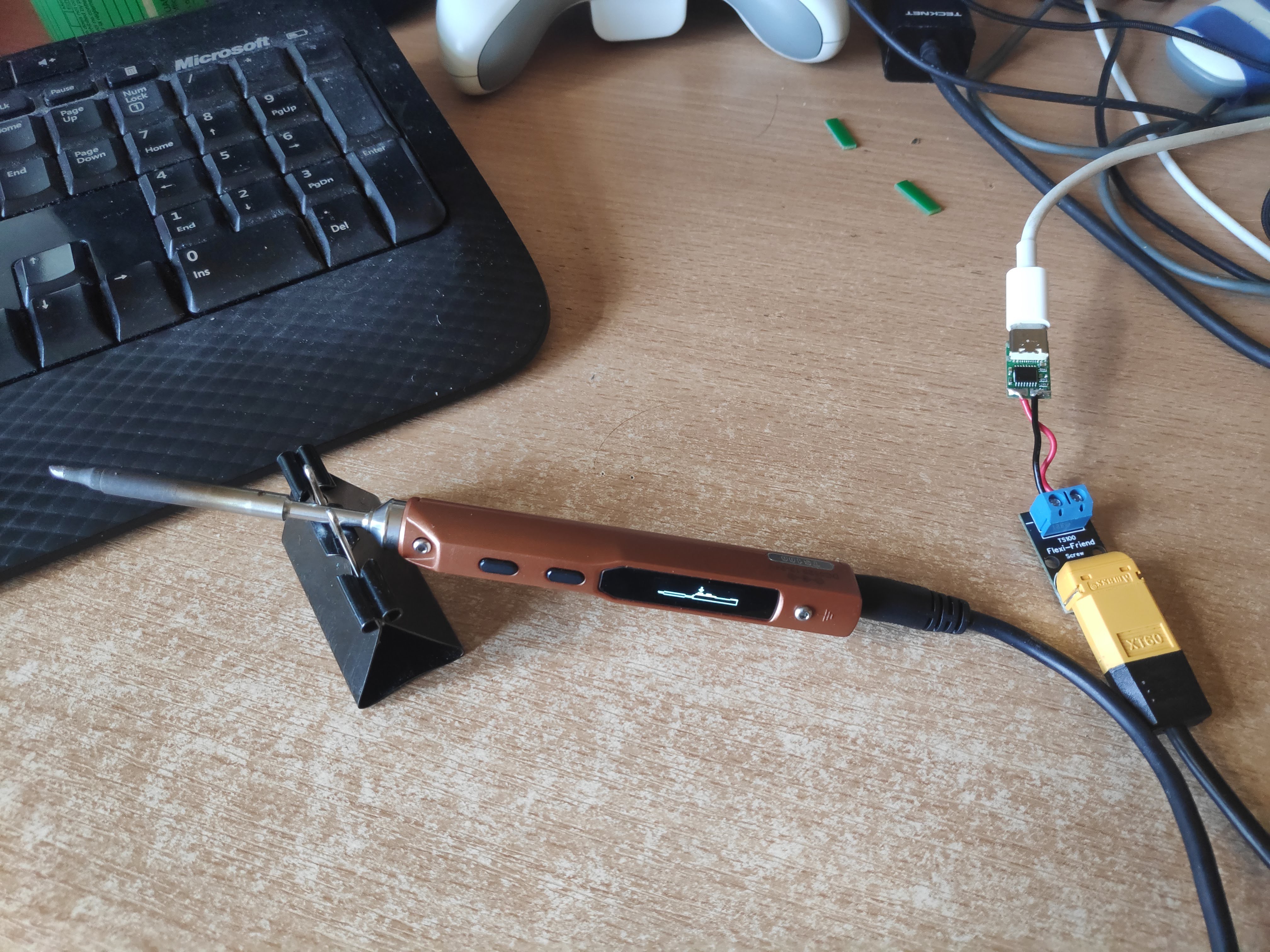
I've been working on a solution for this that I would love to get feedback on

img

One of the main features of what I'll be doing is incorporating an XT60 connector into the PCB so it can be used with the existing battery cables available, I find them very flexible and good to work with compared to other power supply cables I've used.

I've been doing some prototyping with existing adapters and modules. I haven't power my TS100 from anything but USB-C in about 3 months! I didn't even unpack my regular supply when I moved.

The above picture above is using an IP2721 Module, and I was happy enough with how it worked, so I designed a PCB using it, but I figured shortly after ordering that I think it will have problems.

The IP2721 only negotiates voltage, which is fine if you have a big enough power supply. But even 45W power supplies are out of spec @20v, although I just received a 45W power bank today and it did work, but it pulled more than 45W (~48W) on heat-up.

I also bought a 30W supply to test which I assume is just going to trigger the over current protection of the supply.

To ensure compatibility with all PD PSUs, the sink IC that is used should also be able to negotiate the current a supply can do, so it can drop to lower voltages if needed. I'm after buying the reference board for the STUSB4500 so I can try that out. That should allow me to configure up to 3 voltage & current profiles, which would allow it to negotiate down to 15V or even 12V if the supply was out of spec.

If people had any comments or suggestions on the project I would really like to hear it!

JennyEverywhere commented 4 years ago

I use this device: https://www.tindie.com/products/clarahobbs/pd-buddy-sink/

With Power Delivery chargers and power banks, to power low-power ham radio transceivers.

I wrote it up here: https://www.ng3p.com/2020/05/a-different-power-source-for-field-ham.html

Perhaps this will be of use. You've got part of what I did, but the Buddy Sink at least also negotiates current and power.

-=-=-=-=-=-=-=-=- 73, Gwen, NG3P

On Thu, Jun 4, 2020 at 5:09 PM Brian Lough notifications@github.com wrote:

I've been working on a solution for this that I would love to get feedback on

[image: img] https://camo.githubusercontent.com/17a9587a4dfc80cc8b8c2f4b377820ea2453603b/68747470733a2f2f63646e2e6861636b616461792e696f2f696d616765732f393838323531313539313237333230313435372e6a7067

One of the main features of what I'll be doing is incorporating an XT60 connector into the PCB so it can be used with the existing battery cables available, I find them very flexible and good to work with compared to other power supply cables I've used.

I've been doing some prototyping with existing adapters and modules. I haven't power my TS100 from anything but USB-C in about 3 months! I didn't even unpack my regular supply when I moved.

The above picture above is using an IP2721 Module, and I was happy enough with how it worked, so I designed a PCB using it, but I figured shortly after ordering that I think it will have problems.

The IP2721 only negotiates voltage, which is fine if you have a big enough power supply. But even 45W power supplies are out of spec @20V https://github.com/20V, although I just received a 45W power bank today and it did work, but it pulled more than 45W (~48W) on heat-up.

I also bought a 30W supply to test which I assume is just going to trigger the over current protection of the supply.

To ensure compatibility with all PD PSUs, the sink IC that is used should also be able to negotiate the current a supply can do, so it can drop to lower voltages if needed. I'm after buying the reference board for the STUSB4500 so I can try that out. That should allow me to configure up to 3 voltage & current profiles, which would allow it to negotiate down to 15V or even 12V if the supply was out of spec.

If people had any comments or suggestions on the project I would really like to hear it!

— You are receiving this because you commented. Reply to this email directly, view it on GitHub https://github.com/Ralim/ts100/issues/24#issuecomment-639117553, or unsubscribe https://github.com/notifications/unsubscribe-auth/AENBU7NUJT2I63MTYK62GU3RVAEQPANCNFSM4DS55KRQ .

Ralim commented 4 years ago

At some point soon I will be adding support for FUSB302 support for the TS80P (once mine arrives).

So one option is a build for the TS100 that has that IC also enabled could be possible. That way the iron can lookup by tip resistance the ideal voltage to negotiate for to ensure that power is within limits.

The STUSB4500 is also a chip i plan to support, but probably a little but further down the line as I havent yet dug into it much yet.

If it were me i would use XT30 over XT60 for this application :)

witnessmenow commented 4 years ago

Thanks @JennyEverywhere , I'm not sure what chip the sink buddy uses, but the stusb4500 is configurable via i2c, so I'm hoping it will suit the needs. The nice thing about the reference board is a I can evaluate the functionality without designing a PCB for it!

Would you be planning to put the ic inside the housing then @Ralim ? I assume you have seen the otter iron project ? (it's on GitHub) it's a complete replacement PCB for the ts100 that enables PD on board.

That's interesting about measuring the resistance of tips, I was just going to base my profiles for the STUSB on a resistance of 8.5Ohm, but I guess there could be variations between tips. The adaptor I build using the STUSB (if it works out) will have the i2c pads exposed so users can change the profiles of they wish.

The XT60 is major overkill for sure, the only reason I'm using it is to take advantage of all the existing xt60 cables that are available for the ts100. Even when I was using my regular power supply I had built an adaptor to use one of these xt60 cables because of how flexible they are, I find them very nice to work with.

I have a ts80p on the way too, so I'm interested to hear about whatever progress you make with it!

Ralim commented 4 years ago

@witnessmenow

The sink buddy actually uses the FUSB302 and its the firmware I'm using as an implementation reference for the support im adding now :)

I personally would mod the IC module inside of the enclosure, removing the usb-micro and trimming the board to fit there (the FUSB is tiny).

Indeed I do know about and love the OtterIron; getting mine running with this firmware is on my infinite to-do list :|

Oh, you can assume 8.5+-0.3ohms roughly; just meant more that since PD has PPS (continuous voltages); its possible in theory to select the highest voltage that just keeps below the power supply current limit worst case :)

I just lopped off the XT60 and put on some nice XT30 connectors 😆

TS80P will get there soon but thats for the other thread 😂

witnessmenow commented 4 years ago

IMG_20200614_074657_782

I received my ip2721 version and all the parts and assembled it. After fixing a mistake I missed from the datasheet (a 100k between vcc and the SEL to set for 20v) it actually works quite well. Changing the SEL pin to floating negotiates 15v.

I did a live stream of assembling it and also testing out the stusb4500 and most of the viewers seemed happy enough with the ip2721 version, which would definitely be cheaper as the chip itself is 1/3 of the price, but the fact it doesn't need to be programmed is a huge time/cost saver.

So I fixed up my design for that and ordered a new version.

Even before I started testing the stUSB I figured that while it supports 3 profiles, which would be perfect for the ts100 as there are 3 pd voltages in the range, profile 1 is locked to 5v. I was able to configure it for 20v and 15v and it did as expected. I probably still will make up a design based on it though

I must look up the FUSB, thanks for mentioning it!

Slightly off topic, but I bought several different wattages of pd supplies for testing this board out. I have 6 of them, and only 2 out 6 (my two power banks) will power the TS80p, despite 5 of 6 being 30w or higher.

My 30w Amazon, my genuine ~60w Mac charger and my fake 87w Mac charger all meet the wattage requirements, but don't offer 12v. So it will be interesting to see how compatible it is with just random pd chargers people have lieing around

puzrin commented 4 years ago

The sink buddy actually uses the FUSB302 and its the firmware I'm using as an implementation reference for the support im adding now :)

@Ralim it would be very useful if you could release your USB PD support for FS302 as standalone lib with MIT license. AFAIK currently there are no useable opensource libs to just ask PPS V/A and nothing more.

witnessmenow commented 4 years ago

image

V1.1 of the IP2721 version fixes the issue with the first version. I think I need to add some ESD protection before I release it though. It's exactly as the IP2721 sample schematic recommends, but it couldn't hurt.

@puzrin There is a board on tindie with source code for the FS302, it seems super complicated though (to me anyways)

https://github.com/ReclaimerLabs/USB-PD-Breakout

puzrin commented 4 years ago

There is a board on tindie with source code for the FS302, it seems super complicated though (to me anyways)

That board's FW is specific kludge of "buddy sink". OS is replaced with blocking delays instead of state machine. This may be acceptable for hobby project, but not acceptable for universal library.

Ralim commented 4 years ago

Its not a kludge of buddy-sink; but more a port of the code from the chromebook kernel tree as far as I figured out. I actually started with that firmware but boy was it a mess. It also barely worked.

I've been porting the buddy sink firmware across to FreeRTOS and most parts of it "look" to work; but still chasing around an issue that some messages are not being received within timeouts. Need to probe the I2C bus but soldering inside the TS80P to those wires is a pain in the ass so haven't committed the time to doing that just yet.

Ralim commented 4 years ago

@puzrin My port will inherit a compatible license to the buddy sink since I've built off that code. But will decide more on that once i get the damn thing working.

puzrin commented 4 years ago

FreeRTOS is still "too much" for library. But if you succeed with battle-tested implementaion for TS80P, that will simplify next modifications significantly.

At first glance lib requirements can be reduced to 1ms timer (instead of RTOS), and use prototread-based approach. That will simplify integration into user apps.

Also (no sure 100%), it may be useful restrict support to PPS mode only. Most of modern chargers go with it. This will simplify lib api to trivial.

Need to probe the I2C bus but soldering inside the TS80P to those wires is a pain in the ass so haven't committed the time to doing that just yet.

AFAIK, this part can be done on devboard, instead of T80P. I could not find ON-FUSB3-STM32, but ZY12PDN triggers with STM32F072F4P6 are available on ali & amazon https://www.aliexpress.com/item/4000420377026.html.

Also found noname arduino board https://www.aliexpress.com/i/4001134933824.html

Ralim commented 4 years ago

@puzrin I agree that FreeRTOS may be overkill; however keep in mind that I'm not here to write universal libraries but instead to try and rollout something that functions well :)

PPS mode only is not an option as far as I'm aware at this point in time. I own 8 USB-PD power sources at the moment, and of them only the two newest implement PPS. A lot of power banks still user older designs that only implement PD2.0 standard. So if anything is going to be cut it would be PPS as PD3.0 still includes the fixed voltages of PD 2.0.

I am well aware of the development boards and have ordered some. But seeing as shipping from china is anywhere from 2-12 weeks at the moment I'm not holding my breath waiting for them to arrive :joy:

puzrin commented 4 years ago

@Ralim

I mean, if you roll stable code, it will be not difficult for me to rewrite it into lib. Buddy sink has Apache licence for folder with PD sack. If you keep it (if you don't push with GPL), that will be awesome.

You are right, i was a bit over-optimisic about PPS support. Most promissing is still Baseus 2C1A 65W GaN charger (35$). Many modern (GaN) chargers still may go with PD 3.0 but without PPS. I've ordered some alternate chargers to check if more cheap PPS alernatives available.

PS. I'd like to have working USB PD PPS for this micro reflow. It eats ~40W at 270C. In that case strict requirement for PPS will be reasonable.

mattkerrison commented 4 years ago

@witnessmenow Any progress on the adapter? I need to upgrade my Power Supply for TS100 and have 2 spare 65w Mac chargers lying around, would love to just use them over buying another single use power supply.

witnessmenow commented 4 years ago

I've ordered a new design with ESD protection and the pcbs were shipped yesterday. I also am waiting on some parts too.

I would hope to have them available by the end of the month

I use my 65w Mac charger also and works great. But just to make sure it's clear (sorry if you already know this) using power delivery limits the power of the ts100 to ~50w. To draw 65w, the ts100 needs 24v, the max PD does is 20v

mattkerrison commented 4 years ago

I've ordered a new design with ESD protection and the pcbs were shipped yesterday. I also am waiting on some parts too.

I would hope to have them available by the end of the month

I use my 65w Mac charger also and works great. But just to make sure it's clear (sorry if you already know this) using power delivery limits the power of the ts100 to ~50w. To draw 65w, the ts100 needs 24v, the max PD does is 20v

Yea, I'm just using a 12v supply currently as its all I have with the barrel jack, so it'll be a huge upgrade anyway. I did order the generic usb-c trigger board from aliexpress and a XT-60 silicone cable to splice together, but if your design has some ESD protection built in I'll probably still grab one.

witnessmenow commented 4 years ago

I've ordered a new design with ESD protection and the pcbs were shipped yesterday. I also am waiting on some parts too. I would hope to have them available by the end of the month I use my 65w Mac charger also and works great. But just to make sure it's clear (sorry if you already know this) using power delivery limits the power of the ts100 to ~50w. To draw 65w, the ts100 needs 24v, the max PD does is 20v

Yea, I'm just using a 12v supply currently as its all I have with the barrel jack, so it'll be a huge upgrade anyway. I did order the generic usb-c trigger board from aliexpress and a XT-60 silicone cable to splice together, but if your design has some ESD protection built in I'll probably still grab one.

Ok cool! One of my first prototypes was pretty much exactly that, seemed to work fine! IMG_20200603_141035

If you buy a Female XT60 connector (which is kind of confusing as the pins are female but the plastic housing is male) you could save splicing the cable. My board will use that same style cable and it will save you some money not having to buy that again!

arren-ru commented 4 years ago

Just want to add a little bit here about TS80P and TS100 being powered by PD power source unit.

I'm using a cable which contains PD Sink PCB in the USB-C connector and has DC5525 connector on the other side and fits perfectly. IMAGE 2020-08-21 20:00:20 Cable a bit tough and gives stable 20V, peak consumption was 40~45W according to power indicator on the display. IMAGE 2020-08-21 20:00:19

By the way DC powered TS100 still has advantages over the TS80 and even TS80P, it is power, which is greater and the possibility to "eat" any power sources even DeWalt's batteries (tried 5Ah battery pack it works fine).

Adrian-at-CrimsonAzure commented 4 years ago

I'm using a cable which contains PD Sink PCB in the USB-C connector and has DC5525 connector on the other side and fits perfectly.

@arren-ru Where might I find this cable? I have a PD-Buddy that I hard wired to a DC jack and this looks way more streamlined.

arren-ru commented 4 years ago

I'm using a cable which contains PD Sink PCB in the USB-C connector and has DC5525 connector on the other side and fits perfectly.

@arren-ru Where might I find this cable? I have a PD-Buddy that I hard wired to a DC jack and this looks way more streamlined.

Unfortunately this cable is not available for now, but you may find similar cables on AliExpress like this one OR this one

ElRoberto538 commented 3 years ago

@witnessmenow

The sink buddy actually uses the FUSB302 and its the firmware I'm using as an implementation reference for the support im adding now :)

I personally would mod the IC module inside of the enclosure, removing the usb-micro and trimming the board to fit there (the FUSB is tiny).

Indeed I do know about and love the OtterIron; getting mine running with this firmware is on my infinite to-do list :|

Oh, you can assume 8.5+-0.3ohms roughly; just meant more that since PD has PPS (continuous voltages); its possible in theory to select the highest voltage that just keeps below the power supply current limit worst case :)

I just lopped off the XT60 and put on some nice XT30 connectors laughing

TS80P will get there soon but thats for the other thread joy

I'm looking at porting IronOS onto the Otter Iron now - have you looked into it at all? I wouldn't want to duplicate work.

Ralim commented 1 year ago

Closing this as we now have USB-C iron options on the market.