Installation Guide For EDDY USB And Eddy Coil
[!IMPORTANT] It is no longer necessary to use the BIGTREETECH fork when using the Eddy. You can now run mainline klipper. The guide that follows assumes that you are running mainline klipper. If you are migrating from the BIGTREETECH fork back to mainline then we suggest erasing all of the configuration and calibration data in your config file (including that within the auto save section) and performing the calibration again while using our latest configuration files.
Index
- BTT Eddy Dimensions and Probe Location
- Compiling Firmware
- Printer Configuration
- Drive Current Calibration
- Mapping Eddy Readings To Nozzle Heights
- Bed Mesh Calibration
- Temperature Compensation Calibration
- Extra Info
- FAQ - Frequently Asked Questions
Video Tutorial
For a video tutorial covering many of the points below, please watch the video located here
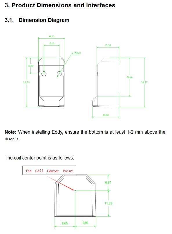
BTT Eddy Dimensions and Probe Location
The Eddy has been designed to mount onto a standard Voron X carriage where the Omron inductive probe would usually mount. Additional mounts are provided for common printers within the 3D folder of this repo. For detailed wiring and mounting instructions for both the Eddy and Eddy Coil, please refer to the PDF manual.
In all cases, mount the Eddy between 2mm and 3mm from the surface of the bed when the nozzle is just touching the bed. Mounting it too close could result in probe errors from the oscillator circuit signal saturating and mounting it too far could result in the oscillator circuit signal collapsing. Use thin shims (such as business cards) to measure this distance approximately.
[!IMPORTANT] When mounting the Eddy, always ensure that the rear (where the electronic components are located) is situated further away from the hotend than the front.
[!TIP] When installing the Eddy (USB version), try to avoid running the cable alongside other cables that are very electrically noisy such as stepper motor cables. If you must run it alongside such cables then do your best to separate the two. If there is slack remaining in the cable, do not wind it in a coil, rather wind it in a figure of 8.
[!IMPORTANT] Some people confuse the current calibration height of 20mm with the mounting height of 2-3mm. The 20mm height is only used when calibrating the coil current later in this guide.
The dimensions below will help you to understand where the center of the coil is when measuring the X and Y offsets from point 15.
Compiling Firmware
[!IMPORTANT] Eddy and Eddy Coil are ONLY compatible with klipper installations that are using a virtual environment based on python 3. Even if you have python 3 installed on your system this does not mean that your klippy virtual environment has been created using python 3. If you receive an error that says something like:
Internal error during connect: split() takes no keyword argumentsthen you have a klippy host that is based on a python 2 virtual environment and you need to get it upgraded. The easiest way to do this is to use KIAUH which will allow you to reinstall the klippy host without overwriting your configs while selecting the python 3 option.[!IMPORTANT] The firmware compilation instructions below only apply to the Eddy USB. If you are using an Eddy Coil then you will have it connected to the I2C port on a toolboard. You will need to compile firmware for that toolboard using the master klipper branch and then install it onto that toolboard. When configuring the Eddy within Klipper you will just need to specify that it communicates using the I2C port on that toolboard which will depend on the pins for that board.
If you are coming from the old BIGTREETECH branch of klipper then we recommend using KIAUH to move back to the mainline branch. We also recommend updating the firmware on all of your klipper devices so that it too is running on a binary compiled from mainline.
- Ensure that you are using mainline klipper by typing the following commands via SSH:
cd ~/klipper
git checkout master
- Next, type
cd ~/klipper
make menuconfig-
Use these settings to compile the firmware.
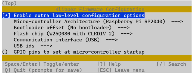
-
Once set, hit 'Q' and when asked, select yes to save.
-
Type
maketo compile. -
Disconnect power to Eddy
-
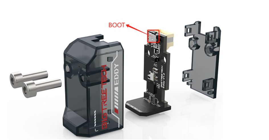
Push and hold boot button on Eddy (Its next to where the cable plugs in) and at the same time, plug in the cable to your BIGTREETECH Pi.
[!IMPORTANT] Don't disassemble your Eddy. The button is fully accessible without disassembly. The image is shown in an exploded view to make the button easier to see.
- SSH into host device
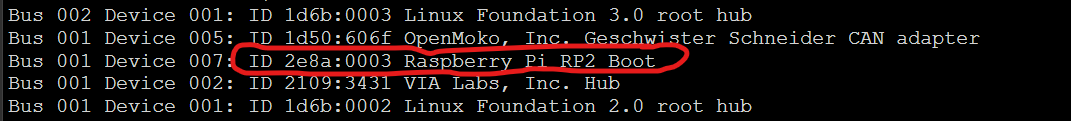
- Type
lsusbinto the command line. You should see eddy.
-
Type
cd ~/klipperinto command line -
Type
make flash FLASH_DEVICE=2e8a:0003Remember to change 2e8a:0003 to your device ID you found in step 9 -
Type
ls /dev/serial/by-id/*into the command line. The found device will be what you enter into your klipper config under [mcu eddy] for the Serial variable. -
Type into command line
sudo reboot
Printer Configuration
[!IMPORTANT] Read these steps well. Following them closely will help to ensure that your installation works without any hassles.
Select the right config file for your needs
- Now that you have the right firmware loaded onto your device, it is time to complete the Klipper configuration. BIGTREETECH provides three different sample configuration files to get you going. You will need to decide which one suits your needs the best. Choose the file that works best for you based on the criteria below. Read the comments in the selected configuration file carefully as they will help you to understand how to modify certain parameters to your installation.
- You wish to use the Eddy as a probe but will use another device as the z-endstop - Use this config with no homing
- You wish to use the Eddy as a probe AND as the z-endstop - Use this config which includes homing
- You wish to use the Eddy as a probe AND as the z-endstop and would like to use the beta z-offset functionality - Use this config which includes homing and z-offset
Whichever config you select, copy the entire contents into your printer.cfg file.
Z Endstop
As mentioned in the paragraph above, you can use the Eddy as the z endstop or you can use another device as an endstop. If you decide to use another device as an endstop then set up your homing and endstop according to that device.
- If you want to enable Z-Homing/Endstop for the eddy do the following things:
a. Under your [stepper_z] in printer.cfg change endstop_pin: PA5 to endstop_pin: probe:z_virtual_endstop and comment out or remove position_endstop: 0. Note that your current endstop may not be PA5 so just look for the line that matches your current endstop and change it.
b. Ensure that you have selected the correct sample configuration file and that the entire contents of that file have been copied into your printer.cfg file. Take note that if you are using a KNOMI then there may be some macros that conflict with the macros in the KNOMI.cfg file. To resolve the conflicts, comment out the macros in the KNOMI.cfg file and uncomment the lines from the Eddy macros that deal with KNOMI functionality.
c. Edit the parts of the config file that are unique to your setup. These may be things like those in the list below. Follow the comments in the config file to help you to edit the values so that they work best with your setup.
- MCU serial
- X offset and Y offset
- Mesh_min and mesh_max
- Home_xy_position
[!IMPORTANT] The sample configuration requires you to adjust the x_offset and y_offset to match your probe position relative to your nozzle. You can do that by following these steps found HERE and also by using the images at the top of this guide which show the center location of the Eddy coil. The settings for the standard Voron X carriage mount are included in all sample configuration files.
2. Drive Current Calibration
With the firmware and configuration done, you are now ready to begin the probe calibration.
- Place Eddy Approx. 20mm above the bed. If you plan to use the Eddy as an endstop then you will not yet be able to home with it and you will need to manually move the gantry or bed such that the Eddy is 20mm above the bed.
- From Mainsail or Fluidd run the command
LDC_CALIBRATE_DRIVE_CURRENT CHIP=btt_eddy - Type
SAVE_CONFIGto save the drive current to your config
3. Mapping Eddy Readings To Nozzle Heights
Now that the drive current has been calibrated, the Eddy will be able to obtain readings from the print bed. Klipper needs to know how those readings correspond to the height of the nozzle. The following calibration procedure positions the nozzle on the bed so that the z height is = 0. It then takes readings from the Eddy as it gradually increases the nozzle height so that it can map those readings to known heights. Follow the steps below to perform this essential calibration.
[!TIP] If you ever find that the nozzle is sitting either too high or too low when it is supposed to be at z=0 then performing this quick calibration again will likely solve your issue. There is no need to set a z-offset. Movement of the probe relative to the nozzle through maintenance may result in the need for this calibration.
[!TIP] Choose your own adventure! If you want to run the mapping the manual way then follow steps 22 thru 26 If you want the easy way then simply follow steps 19 thru 21
- Send the command
PROBE_EDDY_CURRENT_CALIBRATE_AUTO CHIP=btt_eddy - Follow the prompts on the klipper UI to lower the nozzle until it sandwiches a piece of paper between it and the bed but be careful not to dig into the bed. The paper should still be able to move with some force applied.
- Click accept and watch as the Eddy performs the mapping. Be sure to send
SAVE_CONFIGwhen it is done. Skip ahead to Bed Mesh Calibration.
[!TIP] Only perform the steps below if you did not perform steps 19 thru 21.
-
Home X and Y axes with command
G28 X Y -
Make sure you dont have a bed heightmap loaded. Send
BED_MESH_CLEARfrom the console to clear the heightmap. -
Move Nozzle to Centre of the bed with
G0 X125 Y125 F6000. The given command assumes a 250x250 printer but you will need to adjust it for your bed size. Take your bed size and divide it by 2 on X and Y and then use those values for the X and Y values in the command. -
Start the mapping by typing
PROBE_EDDY_CURRENT_CALIBRATE CHIP=btt_eddy. You will see an adjustment box that will allow you to lower the nozzle. Lower the nozzle until it sandwiches a piece of paper between it and the bed but be careful not to dig into the bed. The paper should still be able to move with some force applied. -
Once completed use
SAVE_CONFIG
4. Bed Mesh Calibration
[!IMPORTANT] Before you do this, it's a good idea to perform a Quad Gantry Leveling (Voron etc)
- Home All Axes
- Use command
BED_MESH_CALIBRATE METHOD=rapid_scan - Once completed use
SAVE_CONFIG
5. Temperature Compensation Calibration (Eddy USB ONLY)
[!TIP] The following steps (30-38) are for Eddy USB Only. Eddy Coil doesnt have temperature compensation so these steps should be disregarded.
- Home All Axes and move Z 5 mm above the bed by typing
G0 Z5or using the movement UI. - Set idle timeout by typing
SET_IDLE_TIMEOUT TIMEOUT=36000 - Run
TEMPERATURE_PROBE_CALIBRATE PROBE=btt_eddy TARGET=56 STEP=4 - This will cause the UI to display the z axis adjustment box. Use the paper method mentioned here to pinch a sheet of paper between the nozzle and the bed and then accept the value.
- Turn on your heat bed to the maximum value and your nozzle to 220C.
- If you are in a room with an air-conditioner or an open window, it would be good to turn it off and/or close the window. We want the temperature of the Eddy to rise and breezes will stop that.
- As the Eddy temp rises you will automatically be asked to perform the paper pinch method at each 4C interval. Be careful not to burn yourself on the bed as the bed can get quite hot.
- Repeat the paper test method until the calibration completes. If you find that the temperature of the Eddy is no longer increasing then you can end the calibration early using the relevant command below.
[!NOTE] By default the calibration procedure will request a manual probe every 4C between samples until the TARGET is reached.
The following additional gcode commands are available during drift calibration.
TEMPERATURE_PROBE_NEXTmay be used to force a new sample before the step delta has been reached.
TEMPERATURE_PROBE_COMPLETEmay be used to complete calibration before the TARGET has been reached.
ABORTmay be used to end calibration and discard results.[!TIP] The Eddy thermal calibration process not only accounts for Eddy probe drift but it also accounts for thermal expansion of the mechanical components within your machine. This expansion can be very significant and it can result in poor first layers when using other probes. It is important to keep in mind that if you perform the thermal calibration with the nozzle and the heated bed turned on then there will be thermal expansion from both the hotend and the heated bed. Therefore, if you later try to perform a paper test and only have either the nozzle or the heated bed turned on you may find that there is about a 0.05 gap (not enough to cause a first layer issue but enough to feel less of a pinch on the paper). If this all sounds a bit confusing then don't worry. All you need to know is that you should perform the calibration with the bed and the nozzle both hot and then subsequently print with the bed and the nozzle both hot and you will get fantastic first layers.
- Youre all done and your Eddy will now give you a beautiful first layer across a wide temperature range! :)
Extra Info
Z-Offset
[!TIP] This section only applies to those who are using the Eddy for homing.
The Eddy should not need the use of a z-offset since it is calibrated to understand where z=0 is. Nevertheless, if you would like to use a z-offset then you should use the sample config file that includes z-offset functionality.
To determine the correct Z-offset, follow the steps below.
- Home your printer.
- Place a piece of paper beneath the nozzle.
- Use mainsail or fluidd to set the z height to
z=0. DO NOT babystep to get the nozzle toz=0! Set it as the z-axis height. - After setting the z-axis height to
z=0check if the pinch on your paper is just right. If not, then use babystepping to go up or down. - After babystepping to the correct height, save the adjustment using the button on the mainsail or fluidd UI.
Bed Mesh Calibrate Parameters
The Eddy allows you to perform a very rapid bed mesh scan before each print to ensure that you get the best first layer possible. To do this, we recommend replacing the standard BED_MESH_CALIBRATE macro with our modified version from the sample configuration file and then including a BED_MESH_CALIBRATE call in your print start macro.
To find out more about the parameters used in the bed mesh scan you can read the Klipper documentation here: Bed Mesh Calibration
Bed Mesh Scan Height
The scan height is set by the horizontal_move_z option in [bed_mesh]. In
addition it can be supplied with the BED_MESH_CALIBRATE gcode command via the
HORIZONTAL_MOVE_Z parameter.
The scan height must be sufficiently low to avoid scanning errors. Typically
a height of 2mm (ie: HORIZONTAL_MOVE_Z=2) should work well, presuming that the
probe is mounted correctly.
It should be noted that if the probe is more than 4mm above the surface then the results will be invalid. Thus, scanning is not possible on beds with severe surface deviation or beds with extreme tilt that hasn't been corrected.
Rapid (Continuous) Scanning
When performing a rapid bed mesh scan there is little time to accumulate many samples per point so that they can be averaged and have noise removed. Therefore a rapid scan may not be as accurate as a standard bed mesh scan but in most cases it will still produce a fine first layer.
Rapid scans can be improved by allowing the travel planner to slightly overshoot the scanned bed mesh and smooth the moves. You can configure this overshoot in the bed_mesh configuration section using the scan_overshoot: parameter. Note that you will need to ensure that the axis can travel to the mesh boundary plus this overshoot value on your printer so be careful not to specify a value that is too high. Usually 8mm is plenty.
FAQ - Frequently Asked Questions
Sometimes I get Error during homing probe: Eddy current sensor error
- This generally indicates that the oscillator within the Eddy sensor is not at a valid value before the probe/homing attempt starts. We recommend trying the following steps:
- Double check your probe height. It may be that it is too close to the bed or too high. Remember that we recommend that it is at 2mm-3mm above the bed when the nozzle is just touching the bed. Around 2.5mm is optimal in most cases but if you are finding that your probe is having errors at high temperatures then try to drop it just below 2mm. However, if your probe is having errors during QGL attempts then you may need to raise it slightly.
- After you have adjusted the probe height, remove all of the calibration settings from your config file and recalibrate the eddy.
- If you still receive this error then increase the
reg_drive_currentvalue to 16 from 15 if it is currently set to 15.
Sometimes I get a "Probe Triggered Before Movement" Error
- This will happen when you try to execute two successive
PROBEcommands. Always raise the gantry by a few mm betweenPROBEcommands to avoid this.
Eddy is performing Z Hops or pausing when running Bed Mesh
- Make sure you are using the correct macro call.
BED_MESH_CALIBRATE METHOD=rapid_scan - Remove or alter KAMP - Adaptive Bed Mesh and any custom BED_MESH_CALIBRATE macros. Use klipper adaptive mesh instead or alternatively do not include KAMP/Adaptive_Meshing.cfg in your KAMP_Settings.cfg Information on Adaptive Mesh Here
Which Eddy version should I use?
- It depends on your needs. Eddy USB and Eddy Coil are nearly identical, however Eddy Coil is more for toolhead boards and connects via I2C connectors.
- Eddy Coil does not have temperature compensation and so it may be less reliable for homing if you are using it within a sealed chamber..
Error: gcode command < ANY GCODE COMMAND > already registered
- This will happen when you have conflicting gcode macros. Check all of your gcode macros for ones that share the same name and arbitrate the conflicts. Generally, you should select the functionality from the Eddy macros if there is a conflict and you are not sure what to do.
My z-offset doesnt seem to save and resets, is there a work around or fix?
- Coming from a standard probe, this may seem like a bug. However if you have calibrated the Eddy correctly and are using the special homing macros, then there will be no need for a z-offset. Explaining why is a bit long winded but essentially when it comes to an Eddy, the z-offset parameter does not adjust the height at which the nozzle prints, it just adjusts the height at which homing or probing triggers. If you have a mind that enjoys understanding things at a deeper level then here is a writeup to give you something to chew on: Z-Offsets with Eddy Current Probes
- While we strongly recommend simply performing the Eddy probe calibration in order to get a nozzle height that is just right, you can still simulate a standard z-offset by using the Z-offset beta sample configuration file. Simply uncomment any macro that is related to the beta z-offset functionality and you will be able to use the standard mainsail buttons to raise/lower then nozzle and save that height as a z-offset.
My Eddy Macros Conflict With My KNOMI Macros
- The Eddy and the KNOMI share similar Macros. All of the needed functionality for the KNOMI has been built into the Eddy macros. Please comment out the KNOMI macros which conflict and use the Eddy macros.
- Note that you may need to uncomment some lines in the Eddy macros that are specifically included for people who run the KNOMI. Check the macros to see which lines have been commented and then uncomment them if they are needed for KNOMI.
KAMP And Eddy
[!WARNING]
KAMP aka Klipper-Adaptive-Meshing-Purging should be removed from your klipper prior to using Eddy. Please comment out the include line. ie#[include ./KAMP/adaptive_meshing.cfg]from your KAMP_SETTINGS.cfgInstead KAMP has been integrated into klipper as of January 2024 and you should use the ADAPTIVE=1 option in your BED_MESH_CALIBRATION calls. You can find more Information on Adaptive Mesh Here