Clough42 Lathe Electronic Leadscrew Controller
This is the firmware for a lathe electronic leadscrew controller. The goal is to replace the change gears or gearbox on a metalworking lathe with a stepper motor controlled electronically based on an encoder on the lathe spindle. The electronic controller allows setting different virtual gear ratios for feeds and threading.
License and Disclaimer
This software is distributed under the terms of the MIT license. Read the entire license statement here.
Machine tools can be dangerous. This is especially true of machine tools that can move by themselves under the control of electronics and software. You are responsible for your own safety. Always assume that something could fail and cause the machine to move unexpectedly. Keep clear of pinch points and be ready to kill the power in an emergency.
Latest Version
Version 1.4.00 adds the following features and fixes:
- Automatically detect if the ELS hits its max 100KHz step rate and fail safe
- Change the memory map to allow more thread and feed definitions
Version 1.3.01 added the following features and fixes:
- Fix phantom control panel button presses
- Add power button support
- Fix integer overflow for large metric threads
- Prevent mode and direction changes while running
- Smooth tachometer display
- Add support for lathes with separate feed and thread gearing
Project Status
Beta.
NOTE: This is still a work in progress and is subject to change. Hundreds of people all over the world have purchased parts and built their own. That's great! I have had great success with mine, as have others. Building an ELS for your lathe does require require basic electronics and troubleshooting skills, so keep that in mind if you decide to build one yourself.
Documentation
For documentation, please VISIT THE PROJECT WIKI.
Concept
The project is still in active development. The current hardware looks like this:
- Use a TI F280049C Piccolo microcontroller on a LaunchXL prototyping board
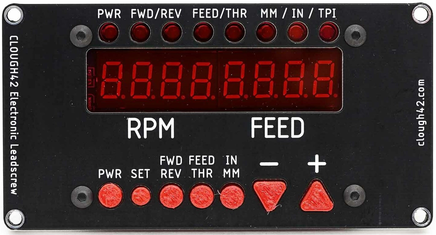
- Use an inexpensive SPI "LED&Key" import display and keypad for the user interface
- Read the spindle position using a rotary encoder with a 3D-printed gear or belt drive
- Use a standard stepper motor (or servo) and driver on the lathe leadscrew
- Make as few modifications to the lathe as possible:
- Use the original leadscrew and halfnuts without machining
- Drive the leadscrew through the factory input shaft
- Drive the encoder from the factory spindle gear train
- Make it easy to restore the lathe to the original change gear configuration
The ELS firmware currently supports the following:
- Feeds in thousandths of an inch per revolution
- Feeds in hundredths of a millimeter per revolution
- Imperial thread pitches (in threads-per-inch)
- Metric thread pitches (in millimeters)
- Imperial and Metric lead screws
- Support for powering down the leadscrew while leaving the tachometer active
- Tachometer averaging (stabilization)
Items on the short list for future development:
- Support for dual-shaft lathes that have different drive ratios for feeding and threading
- Leadscrew speed limit warnings
Possible Future Goals
While this project is starting out as a simple gearbox replacement, some features seem attractive, even for that simple case:
- Threading/feeding up to a hard shoulder with automatic stop
- Automatic recall and resync with hybrid threads (e.g. metric threads on an imperial leadscrew)
Non-Goals
This is not a CNC project. The goal is not to control the lathe automatically, but rather to transparently replace the lathe change gears or quick-change gearbox with an electronic virtual gearbox that can be quickly set to almost any ratio. The lathe will continue to operate normally, with the operator closing and opening the half-nuts to control feeding and threading.
Hardware Configuration
If you want to get this running on your own LaunchXL-F280049C board, here are the settings you will need. See the documentation at the link above for more details.
Physical Switches
The LaunchXL-F280049C has a number of switches on the board to configure the GPIO and peripheral signal routing. This provides lots of flexibility for different uses of the board, but it means that you will have to change some of the switches from their defaults in order to use the GPIO pins and eQEP periperals.
These are the required switch settings
S3.1 = 0Connects eQEP1 to J12S3.2 = 0Connects eQEP2 to J13S4 = 1Connects eQEP1 to J12S9 = 1(default) -- Connects GPIO32/33 to BoosterPack site 2 pins
S6 and S8 can be in any position. 0 is the default.
External Connections
The firmware assumes the following pins are connected externally.
NOTE: the silkscreen on the LaunchXL-F280049C board has the labels for J6 and J8 swapped. J6 is the header closest to the edge of the board.
Encoder
A quadrature encoder for the spindle is connected to the eQEP connector, J12.
Stepper Driver
A Step-direction stepper motor driver should be connected to the following GPIO pins:
GPIO0(J8 pin 80) - StepGPIO1(J8 pin 79) - DirectionGPIO6(J8 pin 78) - EnableGPIO7(J8 pin 77) - Alarm input
Control Panel
The LED&KEY control panel board must be connected through a bidirectional level converter, since it is a 5V device, and the TI microcontroller is a 3.3V device. A standard BSS138-based converter works well.
GPIO24(J6 pin 55) - DIOGPIO32(J8 pin 71) - CLKGPIO33(J6 pin 53) - STB (chip select)
Debugging Outputs
In addition to the control wires for the hardware, the firmware also outputs signals on two additional GPIO pins to allow timing of the interrupt and loop routines. An oscilloscope or logic analyzer may be connected to these pins to debug and time the ISR routines:
GPIO2(J8 pin 76) - Main state machine ISRGPIO3(J8 pin 75) - Secondary control panel loop