TOHKBD rev2
History
When Jolla announced their Jolla phone the mobile Linux community rejoiced and finally had a place to go from their N8x, N900, N950 or N9. Together with the new operating system on the inside, the OtherHalf concept was introduced. With direct data-connection into the phone it is now possible to extend the functionality on a hardware level.
Naturally, a keyboard OtherHalf was the most requested feature by the community by far. Jolla however was still getting started and getting their phone launched with the minimum of Sailors at the time. This was left to the community to develop.
In June 2013 one idiot thought he could easily make this -how hard could it be, really?- and started on his journey. After some time this foolish individual make TOHKBD-rev1: hackish, ugly, frankensteined, terrible durability and way too much work to assemble. But it worked.
After this project ended there was a period of other Funky-TOH development, with during that time a lot of requests of making more keyboards. Little did they knew that in the background the imfamous 'dirkvl' together with his trusty 'kimmoli' were cooking up a new version. A better one. The One.
With an open application on the hashweb/tweetspace Andrew joined the team and provid himself to be the missing piece of the three piece puzzle. With a complete team, a solid design and a strong backing from the rest of the community, the TOHKBD-team set out onto the open crowdfunding sea. And struck gold.
Hardware
Electronics
TOH-cover
In the cover that snap onto the phone there is very little going on. There is a PCB that connects to all 6 pogo-pins. Connecting to these pins is a voltage regulator and an EEPROM.
This is a memory module that contains a Vendor and Product ID. The phone reads this EEPROM when it connects to start the appropriate driver.
If the driver is not installed, the phone reads the NFC tag on the PCB and pulls the driver from the store.
With two contact pads (8mm PCBs) the keyboard piece can make contact, all 6 pins are available.
Keyboard piece
In the keyboard a little more is going on. The main driver is the TCA8424. It runs on 1.8V I2C lines and has three notification LEDs connected, where the TCA8424 acts as an open drain. The LEDs have some probing pads for testing during production.
This connects to the keyboard matrix. It waits untill a key is pressed, then starts scanning and notifies the phone via the INT pin that is has data to be read.
There is an additional EEMPROM in the keyboard piece, containing the keypad layout version. The A0 address pin is pulled high to make it shift one address place and not conflict with the EEPROM in the TOH-cover.
The backlight consists of 10 x 0402 LEDs, controlled with a n-channel MOSFET by the TCA8424.
The keyboard detection is done with a PNP transistor.
1. Phone detects TOH-cover
2. Phone launches TOHKBD driver
3. The driver shuts down the 3V3 line and starts listening to the interrupt
4. When the keyboard connects, the PNP transistor shorts the interrupt line to ground
5. The phone detects the grounding of INT and powers up de 3V3 line
6. The 3V3 disables the grounding on INT in the transistor
7. The phone probes whether the TCA8424 is present
8a. If the TCA8424 is present, the keyboard is present and working and all is set in motion
8b. If the TCA8424 is not present, something is wrong and the phone goes back to step 3
SMD part list:
TCA8424 - QFN40
CAT24C02 - DFN6
IRLML5203 - SOT-3
10K pullup/downs - 0603
10R led resistors - 0603
MCP1700 - SOT-3
0.1uF 6V capacitors - 0603
3.15V highbright leds - 0402
Pogo pins - Mill-Max 0906-0-15-20-76-14-11-0 (Mouser P/N: 575-906015)
PCBs
Made in Eagle Cadsoft. The gerber files are linked below:
SMD assembly
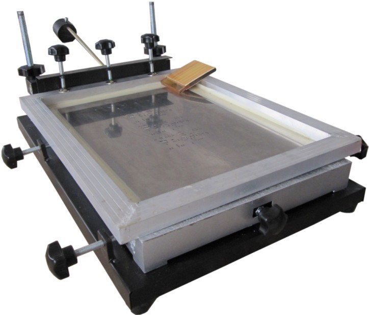
The first step in SMD assembly is applying solder past on the PCB with a stencil printer.

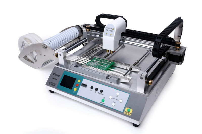
Next a pick&place machine puts the components in the right place on the PCB. I use a TM220A.

Because the accuracy of the machine it not astronomical, the allignment of every component is checked and adjusted by hand if neccessary.
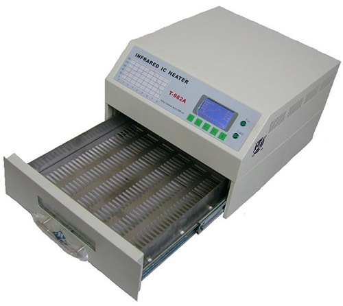
The solderpaste is melted in a reflow oven. (T-962A)

Lastly the PCB is tested manually and all shorts are corrected with a soldering iron.
Frames
The frames are 3D printed (using a process called lasersintering) by Shapeways. If you want to change the colour of your TOHKBD, you can order one of these parts from them:
Cover link Keyboard link
Magnet system
The keyboard part uses magnets to attach and detach in all positions.
The magnets used are the D61-N52 and D62-N52 from KJMagnetics.