User Experience Module
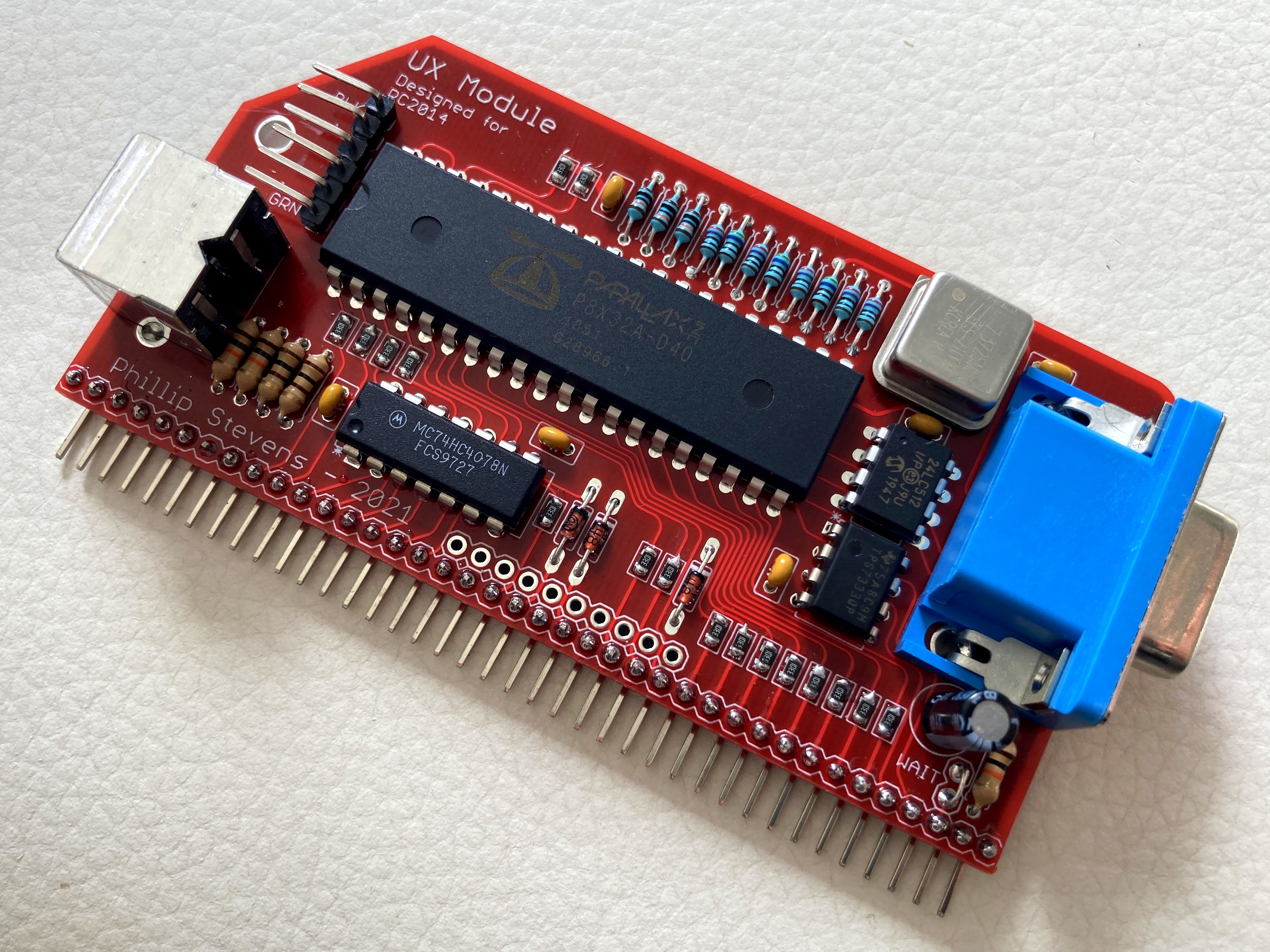
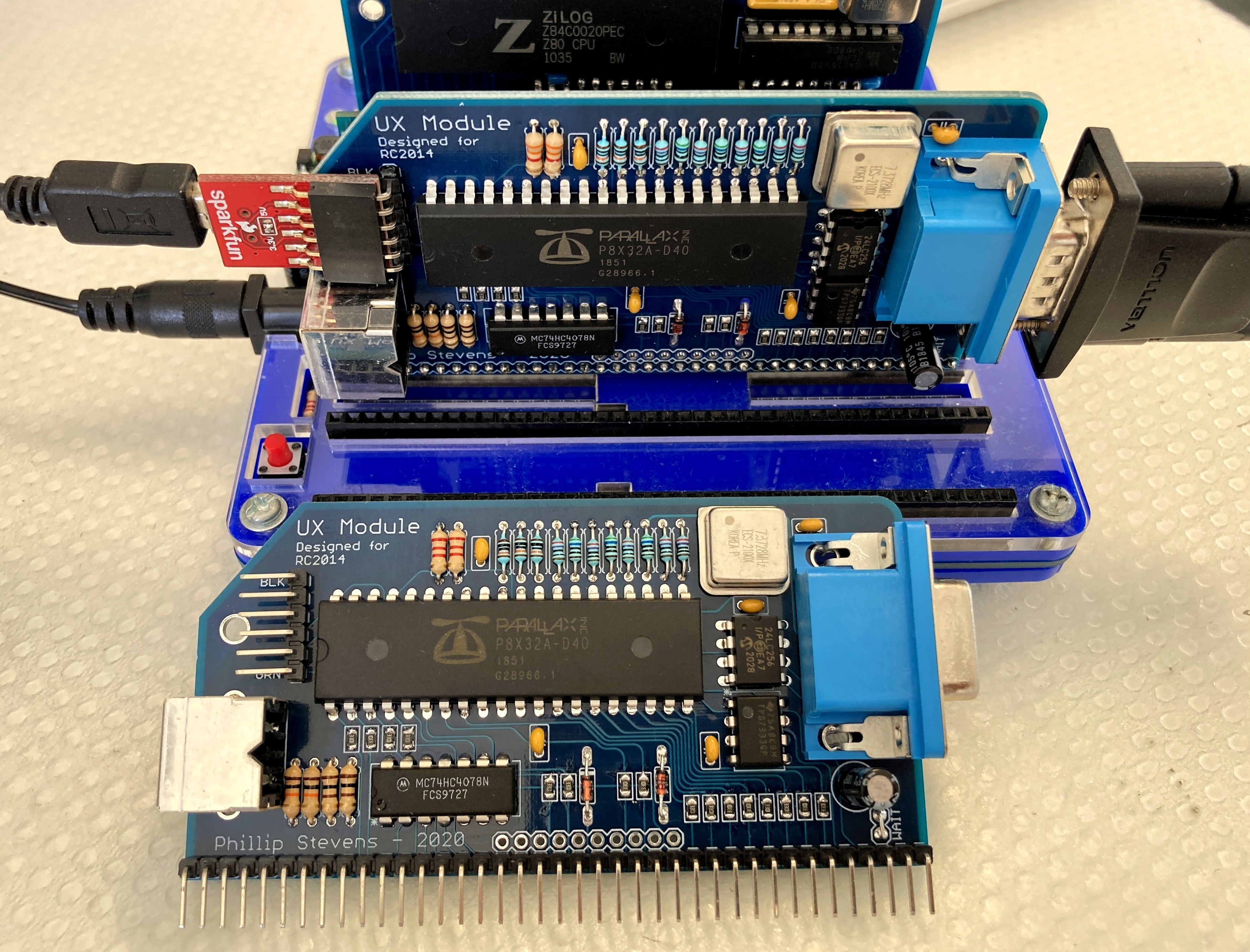
User Experience Module is designed to use with the RC2014.
It provides a VGA output, and PS/2 keyboard input. It also provides a FTDI Basic serial connector, which normally operates in parallel to the VGA/keyboard.
It is designed to operate as an MC68B50 ACIA device (the standard RC2014 Serial Module), so that it can be used without modifying the standard ROMs in circulation.

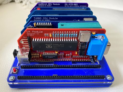
Pictures
 |
 |
 |
 |
Supported System ROMs
RC2014 Standard
The UX Module emulates an ACIA interface on base port 0x80, as per the standard RC2014 usage. Ports 0x80 and 0x81 are required for the implementation.
This supports the use of standard RC2014 ROMs for MS Basic and CP/M as distributed. These ROMs include:
- R - Microsoft BASIC, for 32k RAM, 68B50 ACIA, with origin 0x0000
- K - Microsoft BASIC, for 56k RAM, 68B50 ACIA, with origin 0x0000
- 1 - CP/M Monitor, for pageable ROM, 64k RAM, 68B50 ACIA, CF Module at 0x10, with origin at 0x0000
- 88 - Small Computer Monitor for pageable ROM, 64k RAM, SIO/2 or 68B50 ACIA, with Microsoft BASIC and CP/M boot options
- 9 - Small Computer Monitor for any ROM, any RAM, any UART
CP/M-IDE
The CP/M-IDE for ACIA can be used where an IDE Interface Module is available.
RomWBW
RomWBW is supported, and the UX Module appears as an ACIA port. The UX Module was not compatible with the ACIA device detection mechanism in the 3.0.1 Release, due to the UX Module's tight addressing. However, the device detection mechanism has been improved in the 3.1.1 development branch and it works with the UX Module.
An optimal configuration of RomWBW is to have the UX Module mapped to 0x40, and a SIO Module providing TTY ports. The minimal boot message for this looks like this...
RomWBW HBIOS v3.1.1-pre.43, 2021-02-11

RC2014 Z80 @ 7.372MHz
0 MEM W/S, 1 I/O W/S, INT MODE 1, Z2 MMU
512KB ROM, 512KB RAM

ACIA0: IO=0x40 ACIA MODE=115200,8,N,1
SIO0: IO=0x80 SIO MODE=115200,8,N,1
SIO1: IO=0x82 SIO MODE=115200,8,N,1
MD: UNITS=2 ROMDISK=384KB RAMDISK=256KB
PPIDE: IO=0x20 PPI NOT PRESENT

Unit        Device      Type              Capacity/Mode
----------  ----------  ----------------  --------------------
Char 0      ACIA0:      RS-232            115200,8,N,1
Char 1      SIO0:       RS-232            115200,8,N,1
Char 2      SIO1:       RS-232            115200,8,N,1
Disk 0      MD1:        RAM Disk          256KB,LBA
Disk 1      MD0:        ROM Disk          384KB,LBA

RC2014 Boot Loader

Boot [H=Help]:
To ensure that the UX Module appears as the console port, the console port must be manually set to prefer the UX Module (ACIA) using the BOOTCON configuration. The key elements of the configuration file are noted below.
UARTENABLE  .SET    FALSE       ; UART: DISABLE 8250/16550-LIKE SERIAL DRIVER (UART.ASM)
;
ACIAENABLE  .SET    TRUE        ; ACIA: ENABLE MOTOROLA 6850 ACIA DRIVER (ACIA.ASM)
ACIA0BASE   .SET    $40         ; ACIA 0: REGISTERS BASE ADDR TO AVOID SIO/2 BASE ADDRESS
;
SIOENABLE   .SET    TRUE        ; SIO: ENABLE ZILOG SIO SERIAL DRIVER (SIO.ASM)
SIOCNT      .SET    1           ; SIO: NUMBER OF CHIPS TO DETECT (1-2), 2 CHANNELS PER CHIP
;
TMSENABLE   .SET    FALSE       ; TMS: DISABLE TMS9918 VIDEO/KBD DRIVER (TMS.ASM)
;
BOOTCON     .SET    2           ; SET ACIA AS CONSOLE, ASSUMING 1 SIO/2 MODULE CONFIGURED WITH 2 CHANNELS
Construction
Building the UX Module is fairly straightforward. Some notes are included below describing options and potential issues that may arise.
BOM
The BOM for the UX Module can be found in the Production PCB section of this repository, both listing by parts, and listing by values.
Also, a complete ordering Cart is available at Digikey AU.
Note that the 74HC4078 NOR device is not included in the Digikey BOM. This device is obsolete, but can be obtained from UT Source or other ebay sources (or as an option on Tindie).
Note that sockets are not included in the BOM, but can be used if desired. See the notes on Overclocking below.
SMD
Soldering the SMD devices is fairly straightforward. The resistors go on the front of the board. They are not polarised, but if you are concerned with neatness they can all be aligned so they face the same way. The capacitors go on the back of the board. The 3x 220pF capacitors are mounted behind the diodes, and this can be noted because of the through-hole on either side of the mounting location.
There are many techniques for soldering SMD. For a simple tutorial using a standard fine tipped soldering iron and a pair of tweezers, please refer to this video.
EEPROM I2C
The Parallax Propeller MCU stores its firmware in an external I2C EEPROM. The minimum requirement is for 256kb size (32kB), but the bootloader also supports 512kb size (64kB) devices. Either device is suitable for the UX Module. If you are interested to do additional coding it might be sensible to equip the 512kb device.
There is no need to put the EEPROM in a socket, as it can be programmed in-situ about a million times (literally) and you're never going to need to exchange it.
Overclocking
The Parallax Propeller is specified to run at 80MHz. The typical mechanism to achieve this is to provide a 5MHz crystal or oscillator and use the Propeller internal 16x PLL capability to generate the 80MHz system clock.
Of course this specification can be stretched and the maximum system clock seems to be about 120MHz, noting that this is right on the edge of the capabilities.
The UX Module is expecting a 7.3728MHz oscillator, the same standard clock as the RC2014 Z80, which produces a 118MHz Propeller system clock.
It is possible to use a slower oscillator at 5MHz, or 6.25MHz, or other if desired, or in the unlikely event your selected Propeller device doesn't work at 118MHz. In this case the clock rate specification _xinfreq will have to be adjusted in the firmware to suit, and the VGA video timing will need to be adjusted to suit. If you are concerned about this it would be sensible to mount the oscillator in a socket to enable it to be simply swapped as needed.
Firmware Development
The UX Module firmware is developed in Propeller SPIN, and in Propeller Assembly (PASM). The individual functions are mainly built in PASM, with connecting higher level logic running in SPIN.
Development Environment
There are a number of alternative programming environments for the Parallax Propeller. The PropellerIDE was defined as the default option, and was developed to be cross-platform capable. However, other solutions supporting SPIN, PASM, and C or C++ are also available.
The UX Module is developed using the PropellerIDE, and therefore support will only provided for issues with that platform.
The PropellerIDE is available for Windows, OS X, Linux, and packaged for debian.
Programming Interface
The UX Module provides a standard FTDI Serial interface for programming. This can optimally be at 3V3, but also works at 5V. References to "Prop Plug" in the PropellerIDE should be taken to mean the FTDI Serial device that you're using.
When programming the UX Module firmware, it is important that the upper level code be the active window when clicking "compile and upload". The PropellerIDE will compile and upload a sub-module file if it thinks this is what you wanted (because you left it in the foreground). Of course this will lead to things not working as expected. You'll just need to do it again with the upper most code in the foreground.
Source Code Hierarchy
Propeller SPIN works with modules which help to mask details from driver code from upper level code.
To implement the functions required for the UX Module several SPIN/PASM modules previously written for Propeller by Parallax have been used. This means that the pretested modules from the Parallax "Object Exchange" are used, and that we can focus on how these modules are integrated.
The only (at this stage) special PASM functions written for the UX Module are in the implementation of the ACIA MC6850 Serial Interface. These are in the ACIA module.
ux_module
|
|---> terminal_ftdi
|---> keyboard_ps2
|---> acia_rc2014
|---> i2c
|---> wmf_terminal_vga
      |
      |---> hires_text_vga
Usage Notes
When the UX Module has been programmed successfully, it should boot with UX Module Initialised appearing on both VGA interface (screen) and on the FTDI Serial interface.
To reboot the UX Module the DTR on the FTDI interface needs to be toggled. This can be done with the PropellerIDE, or with any serial terminal that can trigger DTR toggle. This functionality is used by the Arduino family, so the function is quite common within serial terminals.
To reboot the UX module if operating stand-alone, the DTR (GRN) pin can be touched to the ground (BLK) pin on the serial interface, or alternatively touched to the grounded case of the PS/2 keyboard connector.
Once the UX Module is running the ACIA emulation is enabled, so the RC2014 Z80 can now be rebooted. This can be done by pressing the RESET button on the RC2014 or, if a PS/2 keyboard is attached, by pressing CTRL+ALT+DEL. This will now initiate a normal RC2014 boot sequence.
This video below shows the expected output of a session.
CLICK IMAGE TO VIEW!
Ports
The UX Module emulates an ACIA interface on base port 0x80, as per the standard RC2014 usage. Ports 0x80 and 0x81 are required for the implementation.
The UX Module can be alternately located on ports 0x40, 0x41 or on 0xC0, 0xC1.
It will (enhancement plan) be possible to implement a graphics interface (VJET library). It is likely that the graphics interface will use the 0xC0 and 0xC1 ports, and may be configured by settings on other ports.
Video VGA
If you do not have a VGA monitor, it is possible to attach a VGA->HDMI adaptor. The VGA connector on the UX Module supplies 5V to the adaptor so no additional power connection (via USB) is required. The recommended VGA->HDMI adaptor is from Vention and is available here.
The VGA timings (front porch and back porch) have been developed using the Vention HDMI adaptor. If an alternative HDMI adaptor or actual VGA monitor is used, the timings may need to be adjusted to ensure that all characters are visible.
Keyboard PS/2
The keyboard is presumed to be a USA standard keyboard. Alternate key maps are possible, and can be added to your own build of the firmware.
RC2014 Bus Tx/Rx Line Conflict
When multiple serial Modules are used on one RC2014 Backplane, there is a potential for conflict on the Tx/Rx lines, Pin 35 and 36. Conflict on the the Bus Tx/Rx lines will prevent the RC2014 from booting correctly.
The UX Module is connected to the RC2014 Bus serial Tx and Rx lines. When using the UX Module with other serial Modules (such as the SIO/2 Module), it is necessary to disconnect one or other of the serial Modules. In practice the easiest way to do this is to straighten either the UX Module or SIO/2 Module Tx and Rx pins sufficiently so that they do not insert into the Bus connector.
Errata Propeller /RESET Pin
The Propeller MCU /RESET pin is driven by the serial interface DTR pin, which is normally held high when the port is ready. However sometimes both Linux (MacOS) and Windows toggle DTR when opening a new serial interface. This impacts our ability to use the serial interface to upload code to the RC2014.
There are several options proposed on the internet to avoid this issue (mainly driven by Arduino users wanting to have "long running" code). The solutions are written into the serial_tool.py which is included to simplify uploading BASIC programs to the RC2014.
For some machines, none of the software options work so the final solution is to bend the DTR pin out from the FTDI connector. Then an optional connection can be provided to enable Propeller reprogramming. Photos demonstrating one method to do this are provided in the docs directory.
Code of conduct
See the Code of Conduct.