UM3750 Library
An arduino library to emulate the UM3750 encoder/decoder and transmit or receive fixed 12 bit codes over the 315/433MHz bandwidth.
The UM3750 chip and clones were used in many applications, ranging from alarm systems and automated gates to smart sockets. These microchips generate only a baseband output waveform: the actual modulation and demodulation of the signal are left to external circuitry. Most appliances use RF amplitude modulation on either 315MHz or 433MHz, so it is very easy to interface to them with cheap Arduino RF transmitters and receivers.
This library currently supports the ESP8266 only.
How to use
The functionalities offered by this library can be accessed using the class
UM3750; you can create as many instances as you want, but there are some
limitations: see some paragraphs below.
How to transmit a code
Before transmitting your code, you have to set the output pin. Then, besides
setting your code, you can set the symbol duration time in microseconds using
the UM3750:Code struct.
UM3750 myUM3750;

void setup() {
    Serial.begin(9600);
    myUM3750.enableTransmit(D7);
}

void loop() {
    int code = 1337;
    float symbolDurationTime = 741.6;

    myUM3750.transmitCode(UM3750::Code(code, symbolDurationTime));
    delay(500);

    myUM3750.transmitCode(UM3750::Code(code)); // Default symbolDurationTime: 960
    while(um3750.isTransmitting()) yield(); // Wait until the transmission ends

    myUM3750.transmitCode(UM3750::Code(code), 4); // Transmit the code 4 times (Default: 48)
    delay(500);
}
Please note that the symbol duration time should be a multiple of 0.2 microseconds. The default value is 960.
You can choose how many times to transmit the same code by passing the value as
a second argument to the transmitCode function, such as
myUM3750.transmitCode(code, 48);.
By default it is 48 times, which should be enough for most appliances and should
trigger them no more than once.
Also, you cannot use the PWM functionality after calling enableTransmit.
To restore it, you have to call disableTransmit() on every active instance.
How to receive a code
Similarly, before being able to receive a code, you have to choose an input pin.
After a new code has been successfully decoded, you can read it with the
function getReceivedCode, and any new code reception is paused until you call
resetReceivedCode.
UM3750 myUM3750;

void setup() {
    Serial.begin(115200);
    myUM3750.enableReceive(D2);
    Serial.println();
    Serial.println("Listening started");
}

void loop() {
    while(!myUM3750.isReceivedCodeAvailable())
        yield();
    Serial.print("Found code: ");
    Serial.print(myUM3750.getReceivedCode().value);
    Serial.print(" Ts = ");
    Serial.print(myUM3750.getReceivedCode().symbolDurationTime);
    Serial.println();
    myUM3750.resetReceivedCode();
}
A maximum of three instances can be listening at the same time.
To disable code reception for a given instance, you can call disableReceive().
Limitations
This library has got some shortcomings due to some software and/or hardware limitations.
First of all, this library takes advantage of hardware interrupts triggered by a
counter in order to produce an output waveform with reliable timings.
As such, only one transmission can take place at the same time: the function
transmitCode is non blocking and returns immediately if, before being called,
there is not any other transmission going on; otherwise it blocks until all
previous transmissions have finished.
Due to software limitations, only up to three instances can be enabled (on three different pins) to decode an incoming code at the same time. This allows a setup with up to three different listening RF receivers on three different frequencies (eg 300MHz, 315MHz and 433MHz). Even though this number of instances can be increased via software, it should not be necessary in most scenarios; also, as this functionality leverages hardware interrupts on both raising and falling logic value on input pins, the number of input pins and interrupts which can be enabled at a given time may be limited by hardware.
Output Waveform

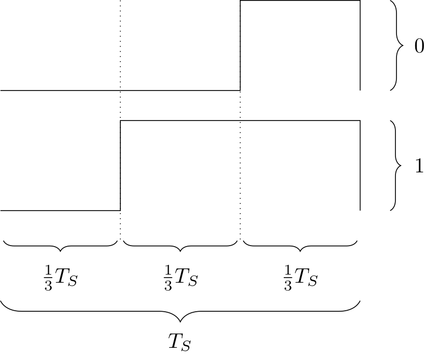
The UM3750 and clones output digital symbols as displayed in the figure on the side.
Each symbol can be decomposed into three parts of same duration:
- The first part is always low;
- The second part is either low or high depending on the bit transmitted;
- The third part is always high.
The symbol duration time Ts can be adjusted on the real IC by changing the value of the RC circuit connected to the input.
The UM3750 IC outputs the same waveform periodically. After some silence and before transmitting the 12 symbols of data, there is a sync symbol, which is equal to a zero symbol. So in total a single output waveform period consists of:
- Silence, whose duration is equivalent to 11 symbols;
- 1 sync symbol;
- 12 data symbols.
