 halirutan
commented
7 years ago
halirutan
commented
7 years ago Let us first review, what hardware wires are coming from the room. Every window in the house has a shutter motor and a pair of push buttons, one button for up and one for down. The shutter motors have 3 wires, one for the ground, one for up and one for down. In the image below you see an overview of my fuse- and switching-box:

You see that I spared the complete lower left corner for the wiring of the shutters and the LOGO. There are two panels in the lower left corner, a blue one and an orange/yellow one. The blue one contains all wires for the shutters which power the motors. The orange panel contains the signal wires from the push buttons. Here is a close-up view

The power lines for the motors from the shutters are thick wires (normal 1.5mm^2 wire) because the motors need 220V and some current to work. The push button wires are only powered by the 24V of the LOGO and they are only used to signal the open/closed state. Therefore, I used cable similar to twisted pair network wires.
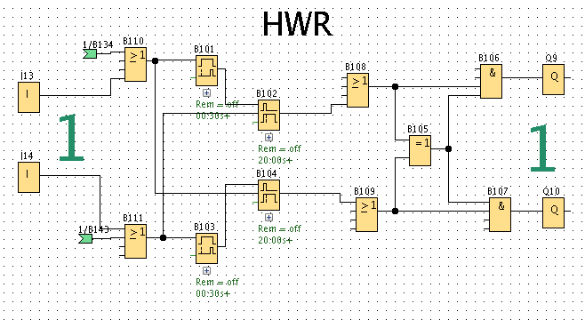
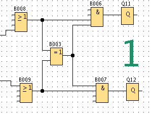
I don't know how to wire the LOGO and the shutter
Let us start with how the shutters go up and down. It's pretty simple. The neutral line of the shutter is connected to the neutral line of the power-network. In the blue panel at the bottom, you see always pairs of blue and gray wires. Blue is for up and gray for down (or vice versa, I really don't know anymore).
As soon as I powered one of these blue or gray cables, one shutter moves. As long as I didn't had the LOGO installed, I could move the shutters manually by using the free floating brown cable in the image. Please don't repeat this! In the blue panel at the top, I combined several shutters which were the windows for one room. So the blue cables at the top of the blue panel (or the holes if there aren't any cable) are short-cut to the blue cable at the bottom.
So the only thing the LOGO has to do is to power up either the blue or the gray wire. Let's look at an image with the LOGO installed

and here a close-up view to see what we need to see

In the last image you see that every blue/gray wire is now connected with a brown/black wire at the top. These brown/black wires are directly connected to the output Qx of the LOGO. The outputs of the LOGO are basically just a switch connecting the 1 with the 2 (look at the labeling at the LOGO). The white wire is just the 220V phase and you see that I just connected them through so that all 1's of the outputs are connected to 220V. As soon as the LOGO closes one of its outputs, the 220V are connected to one of the shutter's up/down wires and the shutter moves.
The signal inputs for the push buttons are almost equally. You use the 24V power source of the LOGO and as soon as you push one of the buttons in the rooms, the specific input of the LOGO gets the 24V signal. You can see in the LOGO overview image, that the DM modules have the small signal cables connected at the top, where the input is.
I hope this clears things up. I'm sorry that I had to explain this in such great detail, but I'm not sure whether the electrical vocabulary I use in Germany fits in other countries as well.
 AppleGeek
Hello, First of all thank you for the amazing project and explanation. I'm trying to make a little project for home automation with LOGO!8 and the integrated WEB Server. Your project helped me a lot in my journey with LOGO!8, but I'm struggling now with the Electrical wiring diagram. I don't know how to wire the LOGO and the shutter and I will need a little help from you, sir.Also can you please tell me what model shutters you use in your project. Thank you for advance!