Shutter-Control
This project shows how you can use Siemens LOGO! 8 modules to create a simple and extendable system to control the shutters in your house.
My electrical installation was as follows: The electrical lines from each window-blind (220V, one neutral line, one for up and one for down) ended in my central power distribution unit. For each window I had a pair of push buttons (not switches!) beside the door of the room; one for up and one for down. The buttons where wired with data-cable which ended in the central power distribution unit as well.
The most simple solution would have been to steer the shutters by connecting the push buttons with coupling relays to the 220V of the shutter lines. With this, the shutters could have been controlled by holding down the corresponding push-button as long as the shutter needs to be closed.
Although my requirements were simple, I wanted a bit more than that:
- it should be possible to close a window-shutter by pressing the push-button for a short time (say 300ms) and then the shutter goes all the way up/down by itself
- it should be possible to open/close all shutters in one room by triple-clicking a push-button of a certain window in that room
- it should be possible to open/close all shutters on the same floor with a triple-click on a specific button
- it should be possible to open/close all window shutters in the house at once
 Hardware set-up and installation
The Siemens LOGO! 8 is a programmable logic controller (PLC) with several analog/digital in- and outputs and the possibility to extend the base module with input-/output-extension modules. Every installed push-button in the house got one digital input and each shutter got 2 digital outputs, one for up and one for down.
To realize this setting, the following components were required:
- 1x Siemens LOGO! Power Module 24V 1.3A
- 2x Siemens Basic Modules 12/24 RCEO 0BA8
- 4x Siemens Digital Extension DM16 24R 0BA2
Wiring
The wiring is straight forward: The push-buttons are driven by the 24V Power Module and when you push a button it sets one of the digital inputs to high. The digital outputs work as switches for the 220V shutter motors and they just power them when closed.
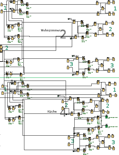
For each floor I used one basic module and 2 digital extensions. The modules need to be clicked together but all this is described in the manually. Therefore, one basic module got the program for the upper and the other one for the lower floor.
My test-program was nothing more that a simple circuit where each digital input is connected to a digital output. With this I could test that all push-buttons and shutters were correctly wired.
Finally, after everything works the two LOGO! Basic Modules need to be connected with a network cable because for steering the whole house they need to communicate.
 Programming LOGO!
Programming the Siemens PLC is done by a proprietary software called LOGO Soft Comfort, a java based graphical application. The file you find in the logo subfolder of this repository can be opened with this program. Circuits are created by dragging and wiring basic and complex logic modules like AND, XOR or DELAYS.
Controlling and locking a shutter
The shutter drives are expensive and hard to change and to prevent damage one of the first steps was to implement a small logic that, no matter what I do, make it impossible that we have current on the up- and downward-wire at the same time.
Therefore, I used a combination of XOR and two ANDs to lock the two outputs. In the following Q11 and Q12 is the output for up and down respectively. You can ignore the ORs B008 and B009 because they are only so that I can have more then one input to open/close this specific shutter:
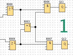
The XOR B003 does only give high (or true) when exactly one of its inputs are high. So when someone accidentally presses up and down, in the ANDs B006 and B007 the wire from the XOR would be low and therefore, no output would be high.
Every shutter has this small component before its outputs. So as long as only up or down is high, the corresponding output is set.
To complete a room with one window, the only two things that are left is the off delay, that makes the shutter go all the way down even if I have released the button and the on delay that only starts a shutter if I have held the push-button for 300ms.
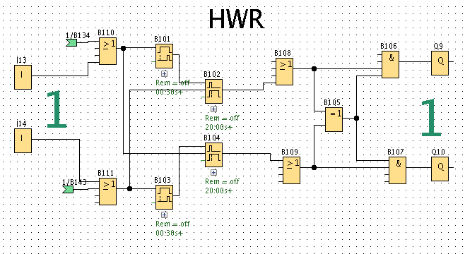
The inputs I13 and I14 are the up/down push-buttons resp. The ORs B110 and B111 are only there so that I can have additional inputs (like when the floor is controlled by another logic). The OnDelays B101 and B103 only set high after I have held the button for 0.3s and the OffDelays B102 and B104 will hold the high for 20s which is the time the shutter needs to go all the way up/down. Note that when one direction is running, a press (no matter how long) on the other direction will stop the OffDelay instantly. This is implemented in the line going from after B111 to B102.
The green flags in the image are the inputs coming when the whole floor is activated.
Implementing a triple-click
Since every push-button is already in use when pressed, I needed a way to give them special meaning. The requirement was that the main-functionality is not disturbed: Every running shutter can still be stopped by a press on the opposite direction or controlled by a longer press as usual.
Therefore, I decided to handle the floor/house control function like it would be a normal input. Just like many people press all buttons manually.
The solution was to implement a triple-click on some buttons which then distribute their high signal to all appropriate windows. The triple-click is implemented with a simple counter and an OffDelay:

The line left of e.g. the OffDelay B038 comes from a push-button. With a button push the OffDelay is started and it holds high for 2s. The high is inverted in B039 and therefore the reset in B037 is not activated. Since the signal is split, every push on the button counts B037 upwards and when it reaches 3, it sets its output to high.
This output is now connected with all shutter inputs it needs to steer. So if this is the triple-click for the upper floor, all shutters of the upper floor will get this output. Remember that each shutter input needs to be held at least for 0.3s to start it. Since every push of the triple-click restarts the OffDelay timer, the inputs are (theoretically) held for 2s. Practically, when the high signal is distributed to all the windows I have incorporated a very small (and different) delay so that the shutters don't start at the exact same time. This is grounded in the fact that electrical motors have a higher start current and I didn't wanted 17 shutters going off the same time. So an important is that the longest delay does not exceed 1.7s to make this specific shutter start.
 Contact
If you have questions, like to discuss details or want to have further information just open an issue here.
Before I started with this project I asked for advice which specific hardware I need in the official German LOGO! forum and very kind help in great detail.