This project is old! I do not recommend my hardware based project anymore, check out my RS-485 protocol-based projects! Main Flipdot Project Page Here

45x7-flipdot-controller
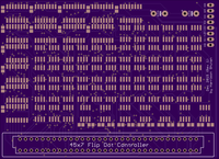
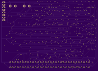
Custom PCB controller board for a single 45x7 flip dot panel from a Luminator MAX3000 SideSign


How To
A much more detailed How To is below
You will need the following items to assemble a flip dot sign using my PCB
- The PCB in this github project which can be ordered from OSH Park or another fab.
- My simple Arduino clock program which contains my
Matrix_CoProcessorlibrary, a library specifically built to drive this PCB. - Surface mount silicon parts: see the Digi-Key BOM file
- Note that the Digi-Key BOM does not include the two through hole capacitors you will need.
- A Luminator MAX3000 Side Sign.
- I purchased mine from Rollsign Gallery. A single Luminator MAX3000 side sign will have two 45x7 display panels inside, which are very easy to remove.
- A microcontroller or Arduino, and various power supply components to provide the different needed voltages.
- I like Paul Stoffregen's Arduino compatible Teensy but often use Arduino Pro Mini clones from eBay for less demanding projects.
Notes
The silkscreen for the 64 pin connector is for aesthetics. You should install the connector on the back of the board not the front, using the silkscreen for orientation reference only.
There are three voltages: Logic (5v), Flip (12-15v), LED (19v or 400mA max)
HW Rev1 of the PCB does not include any current limiting for the flip dots, or for the LEDs. I am using a 60mA current limiter in-line with the flip dot voltage line. The dots seem to flip best based on voltage and not current, which is why I am using such a small current. The LEDs are meant to be driven at 19 volts max, however less is safer. A current limit of 350mA would be safe for the LEDs.
My first prototype clock/sign with this PCB uses 15 volts for both the LEDs and flip dots. This means the LEDs are always on, although not near their maximum brightness. I am using a 5 volt Arduino Pro Mini, and also supplying 5 volts to the logic voltage input on the PCB.
Watch for ground loops, as I believe these cause weak/un-reliable flips. Because the grounds are all "commoned" on the PCB, do not tie any of your grounds together pre-PCB.
Luminator and MAX3000 are trade names of the Luminator Technology Group, not mine.
Detailed How To / Step by Step Instructions
- Acquire a Luminator MAX3000 Side Sign. I found mine on Rollsign Gallery.
- A single Luminator side sign will contain two 45x7 panels.
- Order the PCB in this github project, it can be ordered with a few clicks from OSH Park
- Order the bill of materials (see CSV file)
- Also grab two spare through hole capacitors from your parts bin. Try a 50 volt 330 microfarad for the flip voltage, and a 16 volt 100 microfarad capacitor for the logic voltage.
- Take apart the MAX3000 side sign and remove both of the 45x7 panels.
- Assemble the PCB by placing all components and soldering. Hot air can be used for all the surface mount components.
- For aesthetics, the PCB has very little silk screen. Here is how to place components: Pin 1 of each IC is in the lower left of the land pattern when viewing the board from the top (see PCB pictures at the top of this page).
- The 0805 (2012 Metric) pads in the lower right area of the PCB are for the pull-up and pull-down resistors.
- The 0805 (2012 Metric) pads in the upper left of the PCB are for the 0.1 microfarad shift register supporting capacitors.
- Program an Arduino or microcontroller with the test pattern software. A good test pattern to start with is
testPattern2() - Hook up the Arduino per the comments in the code:
- Arduino Uno pin 11, to SER on PCB
- Arduino Uno pin 13, to SCK on PCB
- Arduino Uno pin 10, to RCK on PCB
- Arduino 5v, to 5v+ on PCB
- Connect a power supply (start with 10-12 volts) to GND and Flip+ on the PCB.
- For prototyping, use a constant voltage/constant current power supply. This will allow you to limit the current to 100mA (or less) for safety, and also to test flip reliability at different voltages. If you are using my
Matrix_CoProcessorlibrary that comes with the test pattern software, then there is little risk of a flip dot being energized for more than a few hundred microseconds, however you should still use current limiting of 100mA or less to prevent damage if any paths remain energized for too long.
- For prototyping, use a constant voltage/constant current power supply. This will allow you to limit the current to 100mA (or less) for safety, and also to test flip reliability at different voltages. If you are using my
Thanks
I would like to thank the following sources: