Bose QC35 USB-C mod
This is a repository holding details of how to modify the Bose QC35 headphones to support USB charging/firmware update over USB-C, rather than the archaic micro-USB connector. This mod works with both QC35 I and QC35 II versions of the headphones.
Disclaimer
This mod involves opening and disassembing your rather expensive headphone that you probably really like using. There is a not insignificant chance of you could damaging your headphones in this process. Keep that in mind before you start. For best chances of success: take your time, work on a well lit anti-static workspace.
We don't take any responsibility nor liability for damage when using any information provided in this repository.
Good luck!
Quick start
View schematic and layout online using KiCanvas!
How to get started
You will be replacing the USB daughter board with a new one featuring a USB-C connector. This means there is no modification to the existing USB daughter board, thus (other than enlarging the hole in the plastic housing) this process is easily reversible.
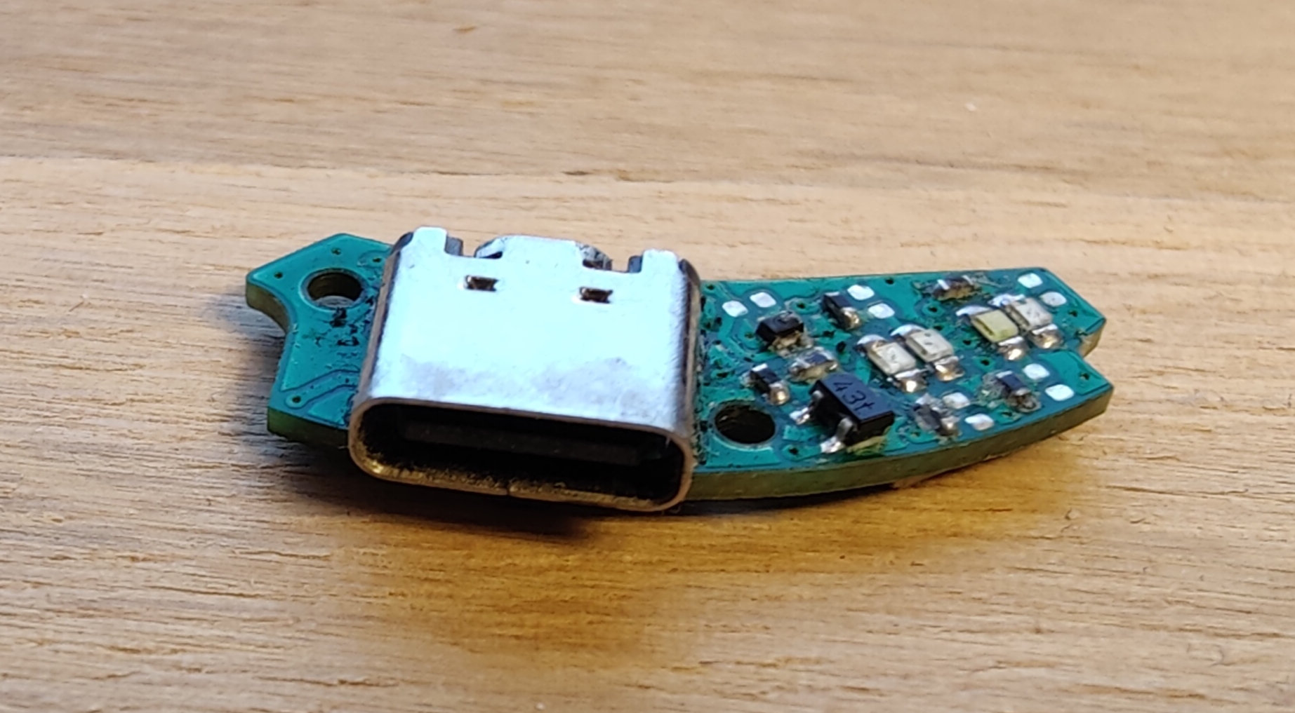
The exisiting USB daughter board has been reverse-engineered and it's schematic has been drawn using KiCad 6.0. All of the source files are provided here if you would like to make any more changes, however the gerber files are also provided which can be sent directly to the PCB fab of your choosing. The thickness of the PCB should be 1mm.
Once you have the sent off for the PCB to be manufactured, you will need to order the parts to populate the PCB with. Some PCB fabs offer assembly also, but I am not sure if any 'budget' PCB fab offer double-sided assembly services. An 'interactive BoM' can be found in the 'bom' directory.
Assembly
Assembly of this PCB is not for the faint of heart. A decent soldering/re-work station, microscope and experience with soldering fine-pitch components are all recommended. The molex connector for the flat-flex to the main board has a pin pitch of 0.4mm. I recommend starting with the passives and LEDs first, working up to the larger ICs and connectors later.
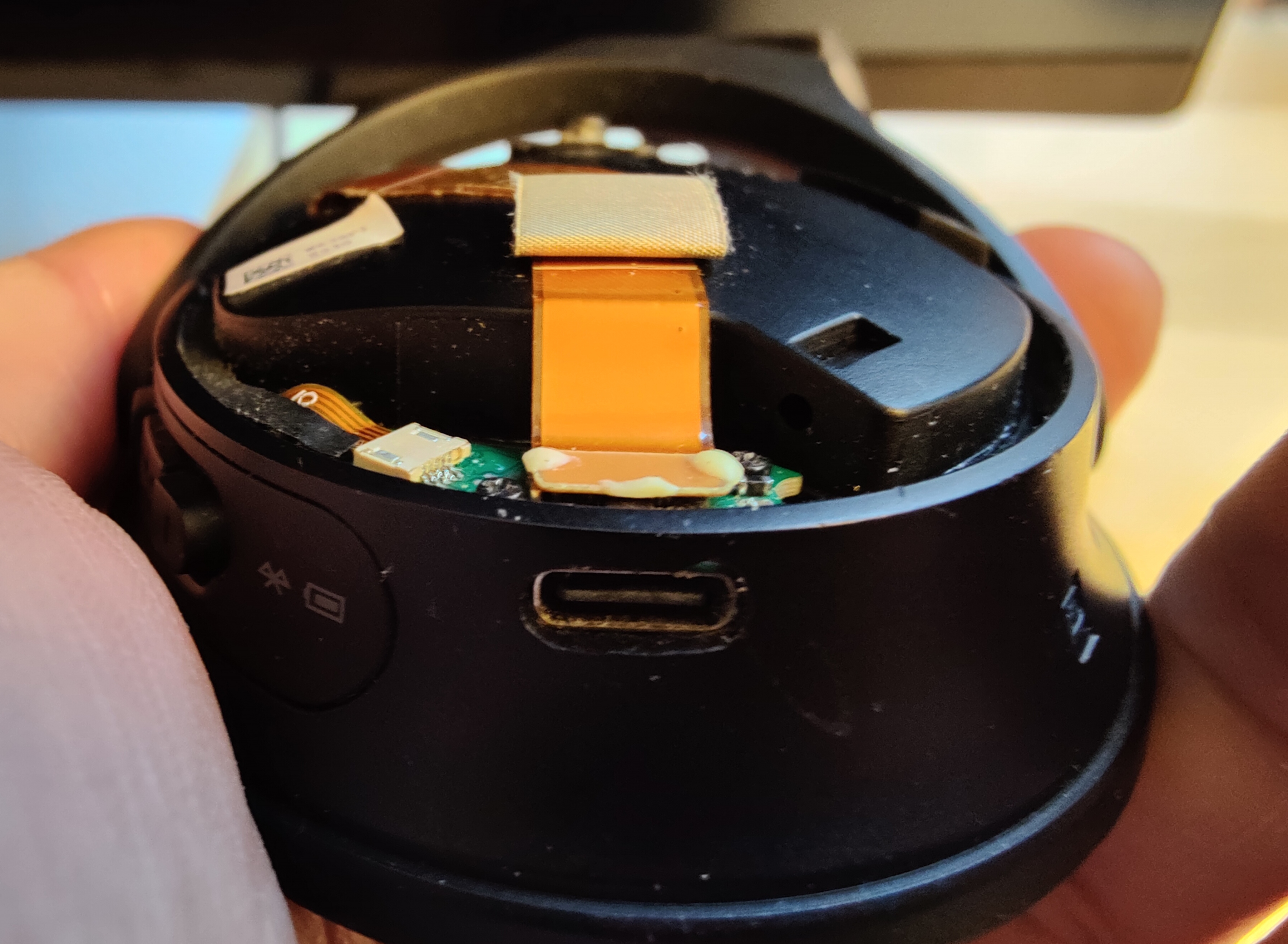
Once you have assembled the PCB you can start to disassemble your headphones to replace the USB daughter board:
- Remove the foam earcup and foam sheet across the speaker grill on the right ear phone.
- Remove the three philips-0 screws holding the metal outer shell in place. This reveals the USB daughter board and mainboard.
- Cut away the silastic holding the cable for the mainboard.
- Remove the mainboard and LED/button board cables from the USB board.
- Unscrew the two philips-0 screws holding down the USB board to remove it.
With the old USB board removed it is now time for the most destructive step. You will need to enlarge the hole in the plastic housing for the larger USB-C connector to exit through. This can be done easily with a rotary tool, or less easily with a small file. Keep checking the fit with the USB-C connector so the hole is not made too big.
Reassemble the headphones by reversing the steps above.