Opentherm IO library for Arduino
Have you ever wondered when and why is your boiler running and heating your home? Do you want to automate your heating system with Arduino? The OpenTherm IO library together with an Arduino OpenTherm shield is designed for you. It will allow you to monitor and control your OpenTherm device with Arduino.
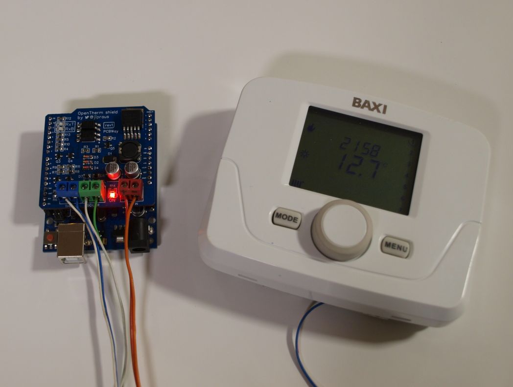
Connect Your Central Heating to Arduino - article describing the use of shield and library.
This repository contains both Arduino library and hardware adapter for OpenTherm protocol 2.2 - see specification.
What is it good for?
- Create your own Arduino-based boiler with an existing OpenTherm thermostat. Most unlikely anybody would do that but it is possible.
- Use the shield to build your own Arduino-based thermostat to fully take over your boiler and home heating. Perfect for home automation. This application only requires an external 5V power supply.
- Place an OpenTherm shield into the lines between the existing boiler and thermostat and create a monitor to watch when and how the boiler is heating your home. You can even intercept the communication to for example wirelessly control the heating.
- OpenTherm allows having a man-in-the-middle device that communicates with both boiler and thermostat. This is how I used the shield to create an OpenTherm regulator.
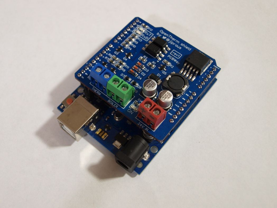
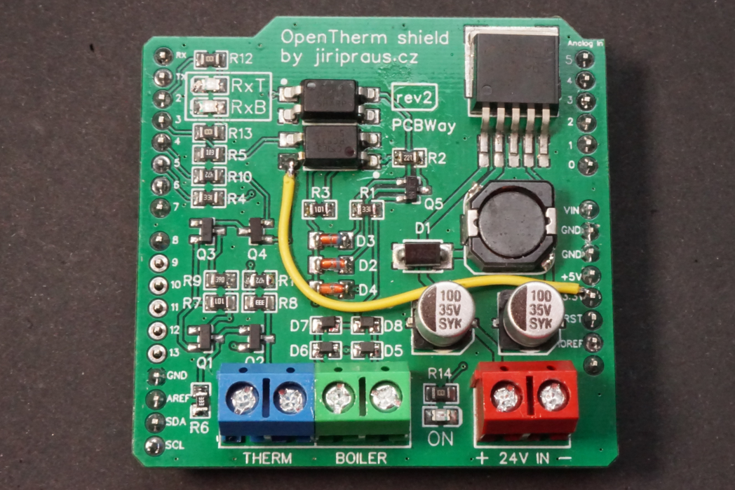
Arduino shield
In order to connect your Arduino board to Opentherm device, you need to create a special hardware interface to convert voltage and current levels for Arudino to be able to handle. Voltage on Opentherm bus rises as high as 24V which would easily burn up your Arduino if connected to wires directly.
Buy or DIY
The easiest way to get the hardware is to purchase a Arduino shield kit from my Tindie store. On the other hand the shield is Open Source so you can manufacture and buy all the components on your own!
Features
- OpenTherm slave interface to communicate with a boiler
- OpenTherm master interface to communicate with a thermostat
- can implement master, slave and gateway modes
- 5V 3A built-in power supply
- Arduino UNO compatible shield
Based on otgw.tclcode.com project.
Fabrication files
Are you able to manufacture the PCB yourself? There are Gerber files included in the repository. Or you can get the DIY KIT from my Tindie store.
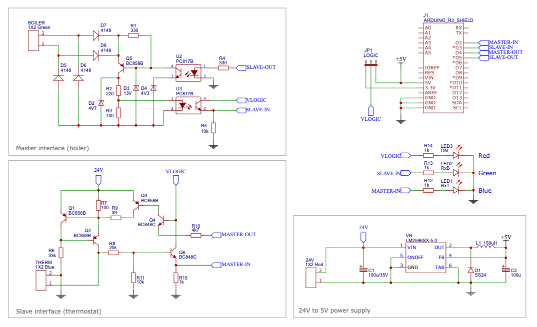
Parts list
- C1 100u/35V electrolytic capacitor
- C2 100u electrolytic capacitor
- D1 SS24
- D2 zener diode 4V7 SOD80C
- D3 zener diode 13V SOD80C
- D4 zener diode 4V3 SOD80C
- D5,D6,D7,D8 - 4148
- L1 150uH CDRH104RT
- LED1 blue 0805 LED
- LED2 green 0805 LED
- LED3 red 0805 LED
- Q1,Q2,Q3,Q5 BC858B SOT-23
- Q4,Q6 BC848C SOT-23
- R1,R4 330 0805
- R2 220 0805
- R3,R7 100 0805
- R5,R11 10k 0805
- R8 20k 0805
- R6 33k 0805
- R9 39 0805
- R10 4k7 0805
- R12,R13,R14,R15 1k 0805
- U1 LM2596SX-5.0
- U2,U3 PC817B
How it is wired up with Arduino
- MASTER-OUT of interface to pin D4 of Arduino
- MASTER-IN to pin D2 (requires pin changed interrupt)
- SLAVE-OUT to pin D5
- SLAVE-IN to pin D3 (requires pin changed interrupt)
- +5V to 5V
- GND to GND
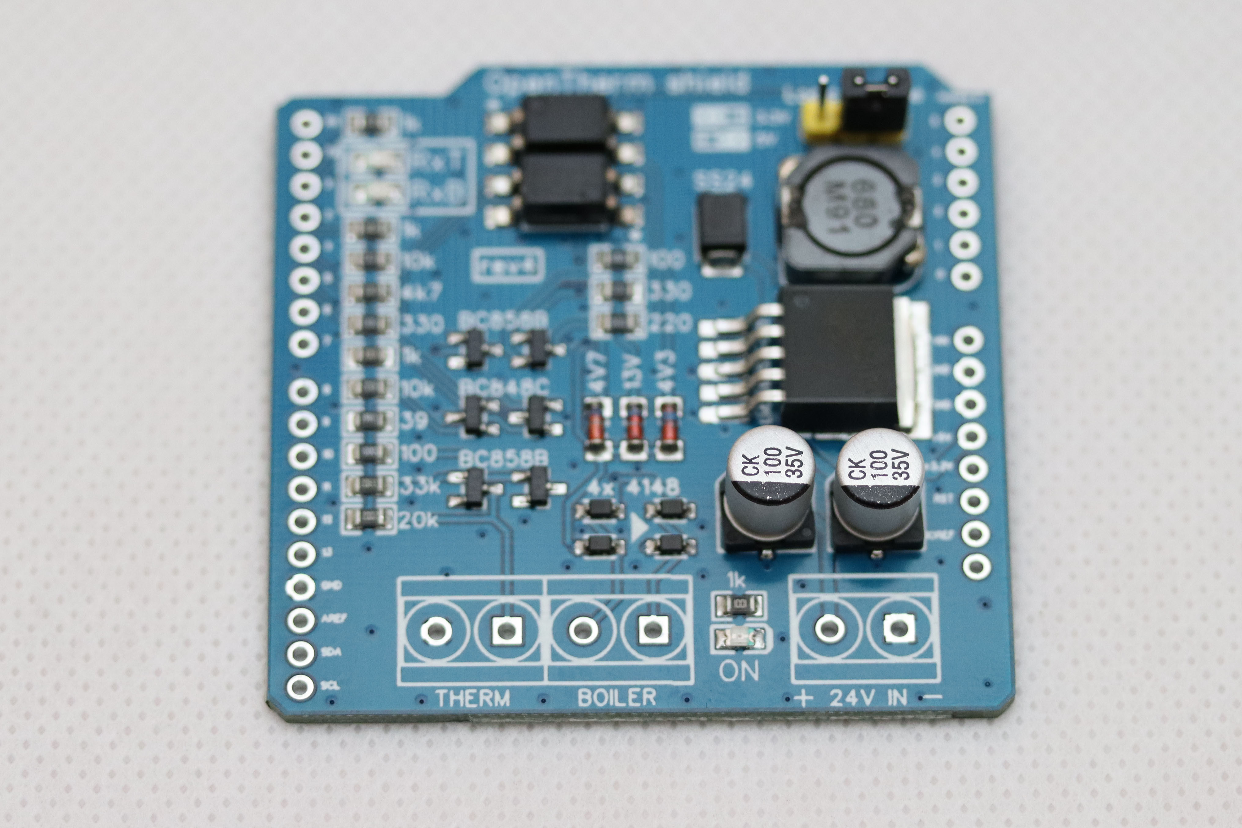
Testing out the hardware
It's not wise to plug the shield with your thermostat or boiler until you test it out. Follow the checks below to make sure your shield is properly assembled. For most of these checks, you will need at least a multimeter capable of measuring voltage, current, and resistance.
The following test works only for 5V version of the board. 3.3V version (Wemos D1) lacks the 3.3V power supply so it does not pass the test without the Arduino board attached. So if you are looking for a 3.3V please build the 5V version first, test out and then update to 3.3V version.
Power supply
- Check whether there is no short circuit between two pins on the 24V RED terminal. Use the continuity function of your multimeter.
- Connect the 24V power supply, keep in mind the polarity of the red connector. Connect the positive voltage wire to + pin (left) and ground wire to - pin (right). Red LED next to the RED terminal will now light up.
- Blue RxT LED will also light up, but don't mind it now. It's perfectly fine.
- Check for 5V between +5V pin (fifth from the bottom on the right side) and ground pin (next one above +5V pin)
Interfaces
Keep the 24V power supply connected.
- Measure voltage on BLUE THERM terminal with a multimeter. It should read 24V. Polarity is not important.
- Next measure current on the same BLUE terminal. It should read a value between 5mA and 9mA. This means a low state of the line.
- If you connect MASTER-OUT pin (digital pin 4 / fifth pin from the top on the left side) to the any of the ground pins, the current on BLUE terminal should increase to a value between 17mA and 23mA. This is a high state of the transceiver line. Outbound thermostat communication is working. Disconnect the pin from the ground.
- Interconnect BLUE THERM and GREEN BOILER terminals with each other with 2 wires. Polarity does not matter at all. This will simulate a boiler for thermostat interface and thermostat for a boiler interface. Measure now voltage on GREEN terminal, it should read a value between 15V and 18V.
- If you re-connect MASTER-OUT pin to the ground again (same as in step 3 above), green RxB LED should light up. Inbound boiler communication is working. Disconnect the pin from the ground.
- If you connect SLAVE-OUT pin (digital pin 5 / sixth pin from the top on the left side) to +5V pin, the blue RxT LED should go off. The voltage on the GREEN terminal should drop to a value between 5V and 7V. This verifies that both outbound boiler and inbound thermostat communication is working.
- Mount the shield on Arduino UNO (disconnected from the computer). It should power up.
- Well done! You are now ready to have some fun with the shield.
Self-test
I've also prepared a self-test program that will test the hardware interface. Download selftest.ino and upload it to your Arduino board. Setup the shield:
- Attach shield to Arduino
- Connect 24V power supply
- Interconnect BLUE THERM and GREEN BOILER terminals with each other with 2 wires.
Self-test result should be:
OpenTherm gateway self-test

Boiler inbound, thermostat outbound .. OK
Boiler outbound, thermostat inbound .. OK
If it's not, do full hardware test above to identify the cause.
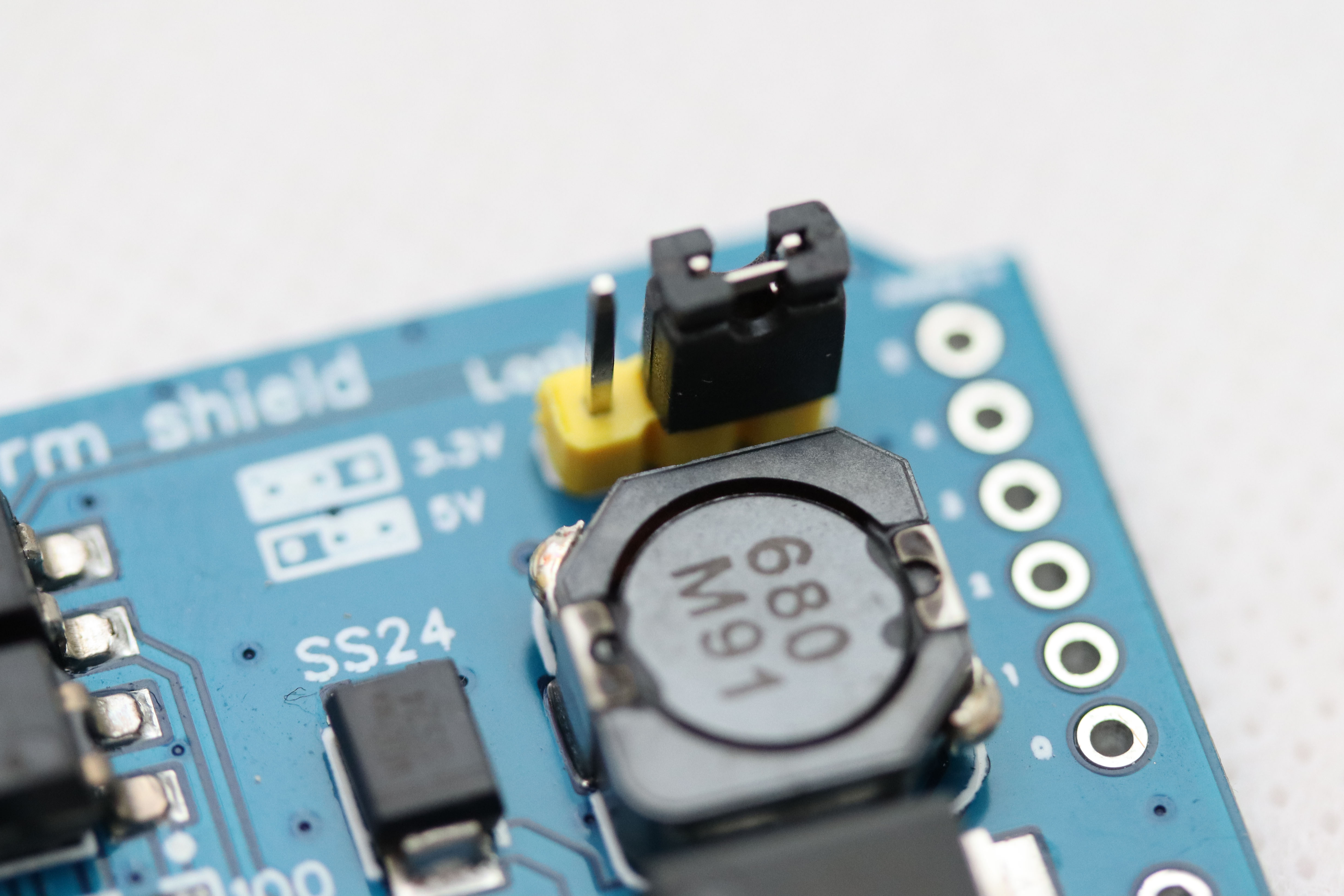
Compatibility with Wemos D1 (ESP8266)
The shield and library code are compatible with a Wemos D1 development board which is using ESP8266 instead of AVR chips. However, ESP8266 is using 3.3V logic so to make the shield work, you need to alter it.
Rev4 boards
- Use Logic Voltage jumper and switch Voltage to 3.3V (left side)
Rev3 boards
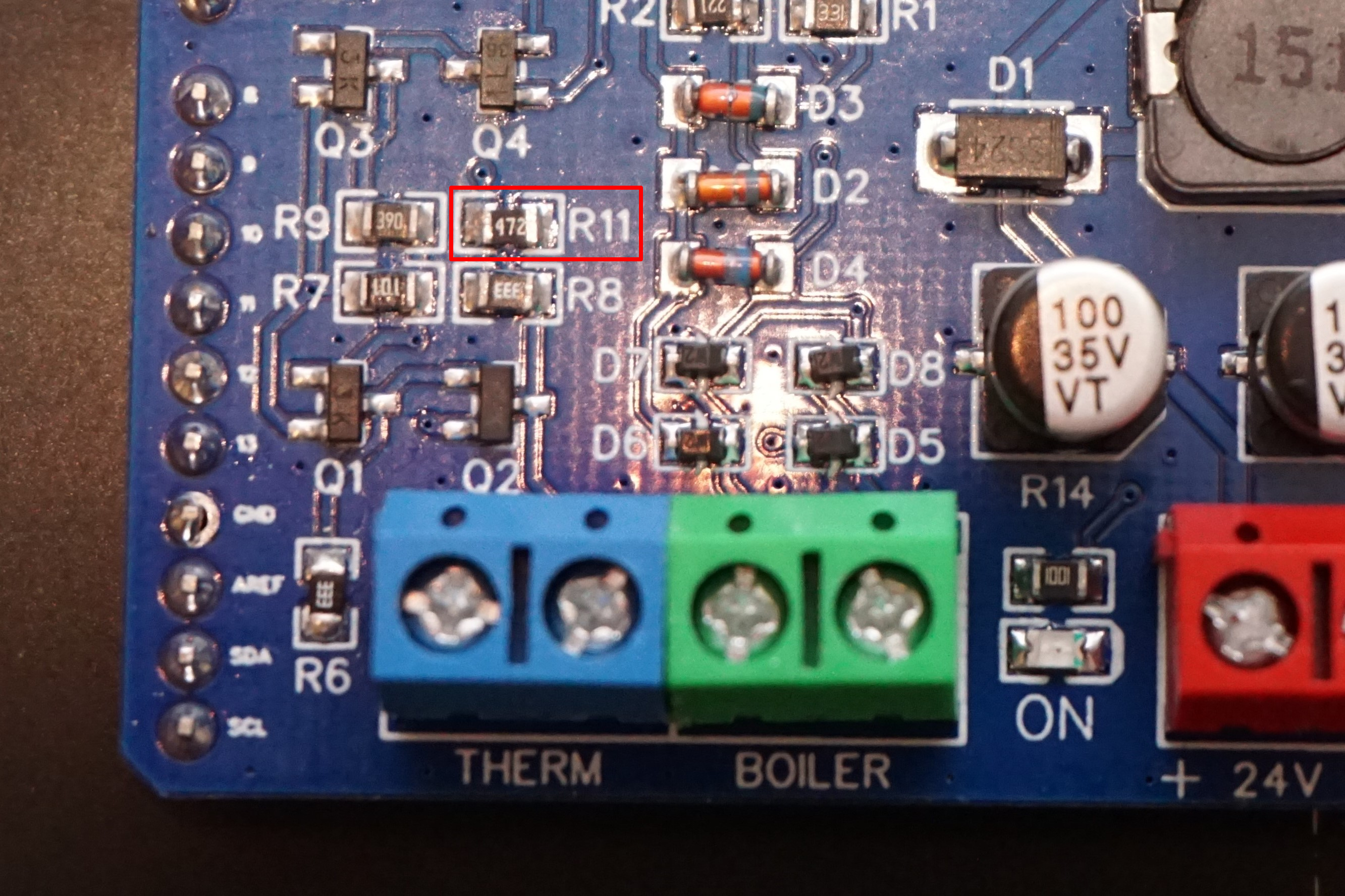
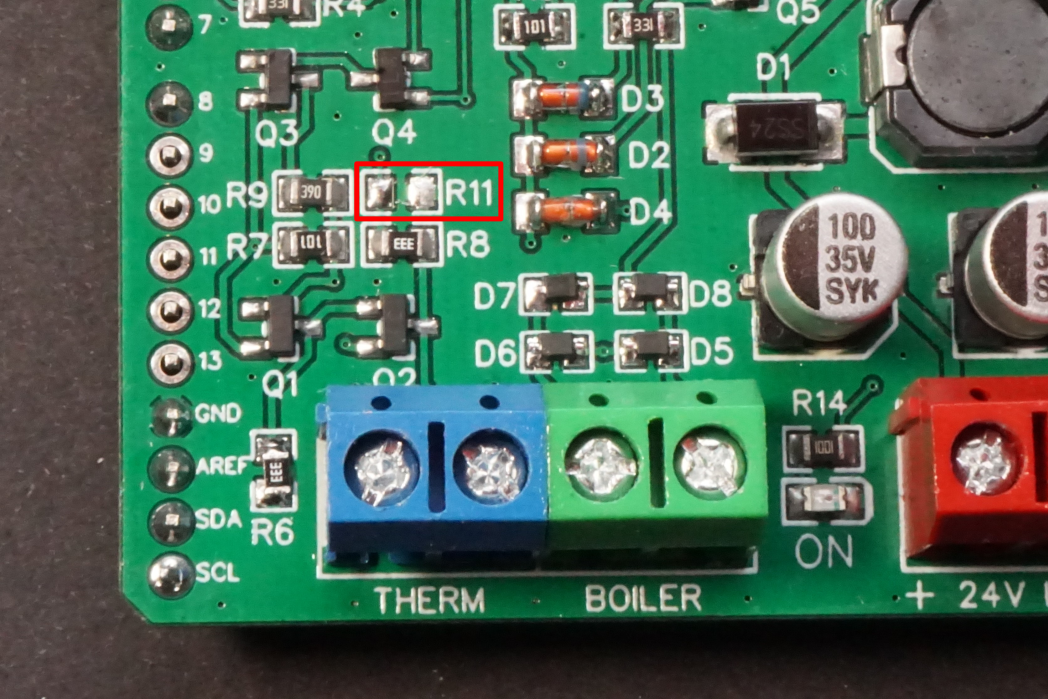
- Replace R11 resistor with 4k7 resistor (instead of 10k)
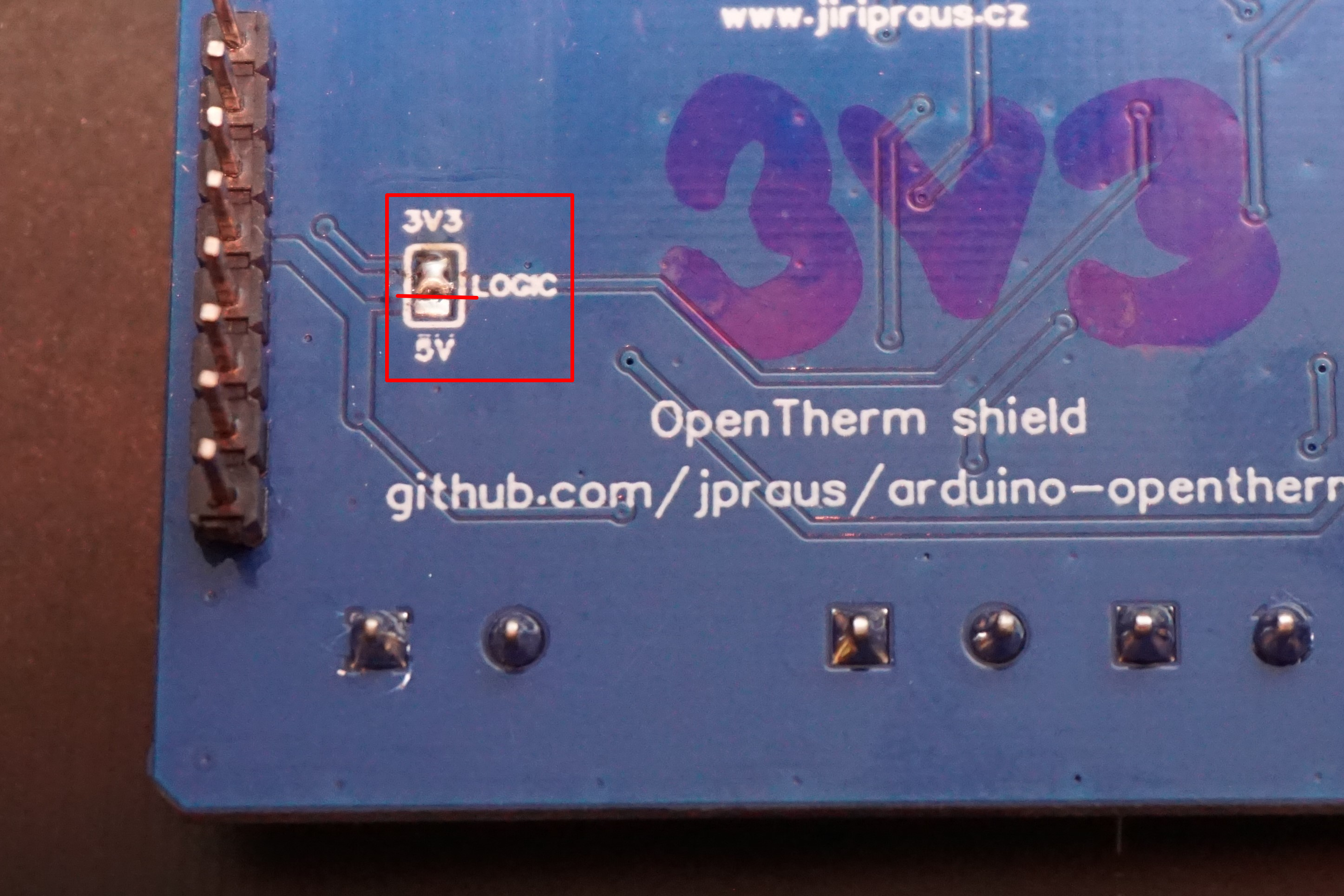
- Cut the 5V jumper on the back of the board
- Solder the 3V3 jumper on the back of the board
Rev2 boards
- Replace R11 resistor with 4k7 resistor (instead of 10k)
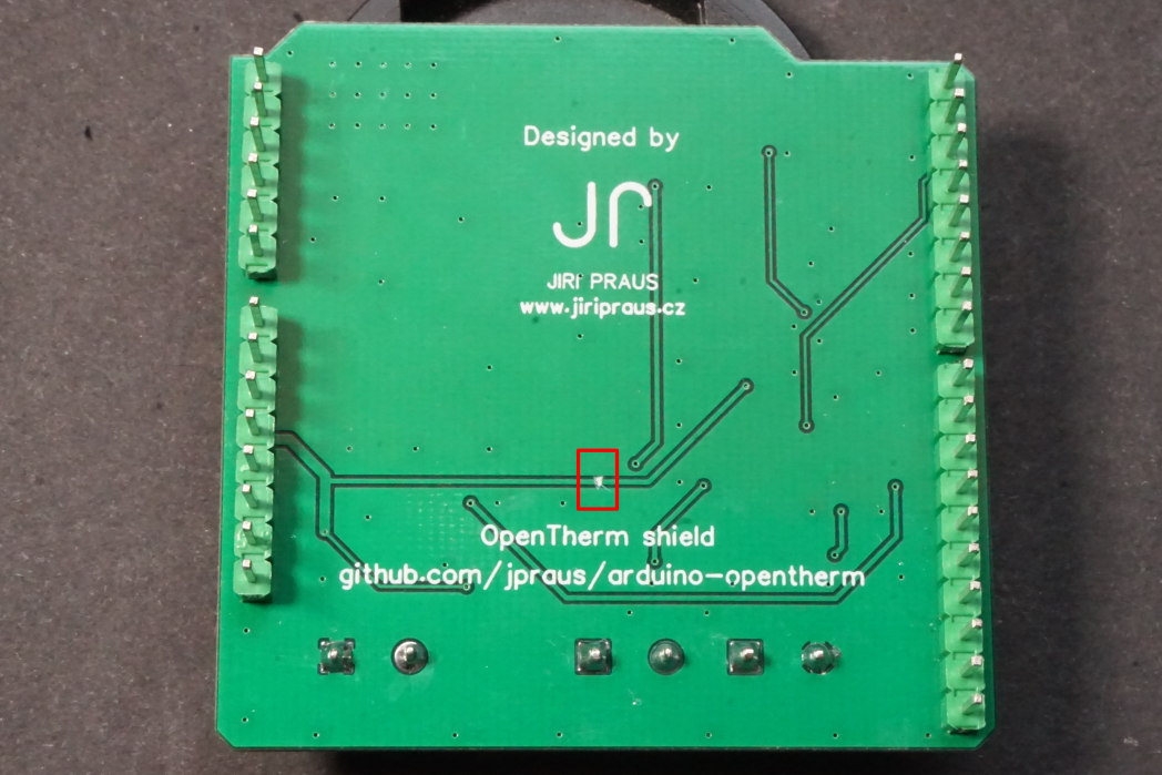
- Cut the 5V trace on the back of the board
- Wire up the optocoupler and the signal transistor to 3.3V with a short wire
Working with library
Library contains 3 examples to test out your setup. These examples are configured to use pins defined above, but library will allow you to change pins to your custom ones.
- master.ino - Arduino acts as master device (thermostat)
- slave.ino - Arduino acts as slave device (boiler)
- gateway.ino - Arduino acts as gateway between master and slave devices
These examles should give you enough information to build your own code using Opentherm library. Check out header file of library source code to see methods documentation.
Behind the scenes
Library uses following Arduino resources:
- Timer2 - to properly read and write encoded data bites to bus
- Pin changed interrupt - bus is monitored for incomming data packets in order to save precious computing time on CPU. Only digital pins D2 and D3 are capable of this functionality on Arduino Uno and Arduino Nano boards.
Note that you won't be able to use libraries that are using Timer2 or pin changed interrupt together with this library (for example Servo library).
Tested with Arduino Nano and Arduino Uno boards.
Warning
Please be aware that using this hardware can damage your boiler or thermostat. You may also void your boiler warranty by installing this hardware. Please consult with your boiler manufacturer. I am not responsible for any damage caused by this shield.