CosmeticThread3D
Version: 0.3
FreeCAD version supported: 0.21.2 or higher
Author: Martin Prokš
e-mail: martin.proks@proks-martin.cz
2024
Forum link: [Feature discussion] Cosmetic thread - 3D geometry - FreeCAD Forum
Git link: GitHub: FreeCAD tool - cosmetic thread for 3D geometry - experimental
FreeCAD tool - cosmetic thread for 3D geometry - experimental.
This tool should make 3D representation and important parameters of cosmetic threads (internal and external) for standard threads to the FreeCAD.
How to use it
Workbench installation
Find path to Your FreeCAD Mod directory. You can find it by typing command App.getUserAppDataDir() in the Python console.
Create folder Mod/CosmeticThread3D and copy there all data from this git repository.
Restart FreeCAD and the workbench should be there.
This tool is under developement. It is not usable for real work yet - some important interface parameters are changing or added or removed during the developement.
But testers and feedback from them is very helpfull and important. Please test it and left a feedback. Thanks.
Usage
For normal usage form GUI follow documentation: user-manual.html
For usage from python console follow documentation: How-to-use-it-from-python-console.html
Video (little outdated, but the main workflow remains): Cosmetic Thread 3D tutorial - Part version - flange and studs
Main idea
Some users (and 3D geometry) does not need true shape of threads in the model. We need just clear visual information like: this hole is not simple hole, this is threaded hole with thread nominal dimension MX and length Y mm. Or this cylindrical end of shaft/bolt/pin/whatever is threaded MX length Y mm. This level of information is enought for drawing making and later machining. (Plus informations about required tolerances and roughness.) And it is enought to visual check if the nominal diameters and lenghts of threads are OK in the mating parts like bolt+nut in an assembly.
True shape of the thread is not necessary to see and the true shape is potential source of problems on a larger models or assemblies. True shape is consuming a lot of computation resources and it is CPU killer in a case of bigger assembly with a lot of screws, nuts and threaded components.
Supported threads
This tool supports some types of threads. Metric Coarse, Metric Fine, UNC, UNF, BSW, G - pipe threads, ... Generally it could support any paralel thread type.
Tapered threads are not supported at this moment.
Visual representation
Generally it is important to see in 3D:
-
Length of the thread.
-
Major and minor diameters of the thread.
-
Optionally some helpfull geometry to better visualisation of the thread (e.g. helix with correct pitch).
Parameters of FreeCAD thread feature
The cosmetic thread geometry is wrapped into one FreeCAD feature (python feature) with parameters for possibility to advanced usage - for example for TechDraw.
The parameters are:
-
Thread designation (for example M10).
-
Nominal thread diameter (for example 10 mm).
-
Pitch (for example 1.5 mm).
-
TPI - threads per inch (for example 16.933).
-
Major diameter and minor diameter for zero tolerances (for example external thread 10 mm / 8.160 mm; internal thread 10 mm / 8.376 mm).
-
Thread length (for example 15 mm).
-
Pre-drilled hole diameter in the case of internal thread (for example 8.5 mm).
-
Tolerances of the thread (for example -6H or -6g).
-
Required roughness of the thread (for example Ra 1.6).
-
Tolerance of lenght of the thread (for example -0/+1 mm).
Implementation
File structure - what is what
-
doc/- documentation... -
icons/- icon folder... -
tests_and_examples/- just some junk-yard... -
Init.py- this file is loaded when FreeCAD starts. It is import of thecosmeticthread3dclass there. -
InitGui.py- the workbench GUI, menus and toolbar buttons. -
__init__.py- rest of macro version of the scripts I started. Not relevant for workbench. -
ct3d_params.py- common parameters definition for all thread versions and types. -
cosmeticthread3d_part.py- all the working code for console mode for Part version of threads. -
cosmeticthread3d_partdesign.py- all the working code for console mode for PartDesign version of threads. -
cosmeticthread3d_Gui.py- GUI buttons and menus called from InitGui.py. -
ct3dGuiTools.py- tools for cosmeticthread3d_Gui. -
MetricCoarse1st.py- tabularized parameters for metric coarse threads, preffered selection (1st) according to ISO 261 -
MetricCoarse2nd.py,MetricCoarse3th.py,MetricFine1st.py,MetricFine2nd.py,MetricFine3th.py, ... - basic geometrich parameters of the threads.
Notes to implementation
Workbench for just two buttons does not make sense in the end. But for the developement of the tools it is most probably the easyest way how to do it. Someday in the future it will be good idea to merge it with some existing and more general work bench - Part WB I think. Or merge it with some other thread oriented work bench?
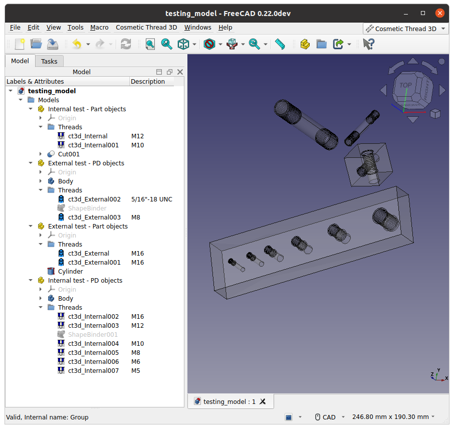
Notes specific to Part version of cosmetic threads: Each thread is separate Part object that could be inserted in a group Threads. It is easy to identify all threads and read their parameters, switch on/off all in once by Threads group. The main solid of the base part is not affected by the cosmetic threads - important for CAM and FEM. But TechDraw can not show curves from model at this moment.
Notes specific to PartDesign version of cosmetic threads: there is no functional version of Cosmetic Thread 3D at this moment. Use ShapeBinder (or SubShapeBinder) and attache the Cosmetic Thread 3D to the binded geometry.
Known issues
-
It will work just for simple holes perpendicular to starting plane. If the starting plane will be under angle to the hole axis, it will be a little bit wrong 3d representation.
-
Not plannar starting surface is not supported (at least yet). No threads to the cylindrical shape or spherical or general surface... Yeas there will be work-aroud with additional circles or datums or lines as hole axis, but again the final representation will be not exactly correct.
-
These problems are common for thread terminantion too.
-
Hole to the thread will be not correct representation.
-
Icons are uggly. Who cares? It is just start of developement, icons are the last thing I care.
-
TechDraw problem. TechDraw does not project curves from model to the drawing. The TechDraw should solve cosmetic thread according its parameters.
-
There is no python report what functions are called on background.
-
There is no language localization, it works in English only.