ArduinoReactionSynchTests
See below , the arduino setup for this firmware

Arduino source code for the Reaction Time Test and Synch Exercise.
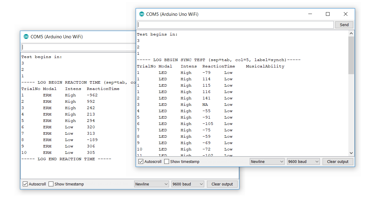
Reaction Time Test
In this test, users are to respond to either LED or ERM stimulus as fast as possible, by clicking a black button on their Arduino board.
The Reaction Time Tests outputs 4 columns.
- Trail No. = Trial Number. After 10 trials the test ends.
- Modal = Modality. Possible values are ERM and LED
- Intens = Intensity. First 5 trials will show 'Low', next 5 trials will show 'High'
-
ReactionTime = The measured reaction time (can be negative if the user pressed earlier than the stimulus appeared).
Synch Exercise
In the Synch Exercise, users have to press the black button in synchronization with either LED or ERM stimulus.
The Synch Exercise outputs 5 columns. The Reaction Time Tests outputs 4 columns.
- Trail No. = Trial Number. After 40 trials the test ends.
- Modal = Modality. Possible values are ERM and LED
- Intens = Intensity. First 5 trials will show 'Low', next 5 trials will show 'High'
- BeatOffset = The measured offset from the beat in milliseconds (can be negative if the user pressed earlier than the stimulus appeared) (the Arduino Monitor mentions this column as ReactionTime).
- MusicalAbility = This is a hardcoded variable that users have to set in the arduino code to reflect their musical ability.