FakeA41
Tasmota enabled DIY Replacement for brp069a41 wifi modules on Daikin A/C units.
USE THIS SOFTWARE AND THE HARDWARE DESCRIBED AT YOUR OWN RISK
I'm not an engineer, it may contains flaws that can cause
any kind of damage.
Hardware
Hardware needed:
- Voltage regulator from about 12V to 5V
- Level shifter 5V-3.3V
- ESP32 based board (tested on Wemos Lolin D32 Pro, ESP32-C3-DEVKITC-02, Wemos Lolin32 Lite)
NB the unit has a 5V pin, but it doesn't seem to be able to supply enough current to run the ESP. See this issue.
The A/C unit plug is as follow (at least on my unit, check yours before connecting anything):
- TX, RX, +12V (unregulated), GND (TX and RX are 5V and won't work with 3.3.)
Circuit:
- Connect 12V and GND to the input of the voltage regulator
- Connect TX and RX via the level shifter to pin GPIO_RX and GPIO_TX of the board (as defined below).
- Power the board (if it have a 5V power input) and the HV side of the level shifter with the output of the voltage regulator.
- Power the LV side of the level shifter with the 3.3 pin of the ESP32 board.
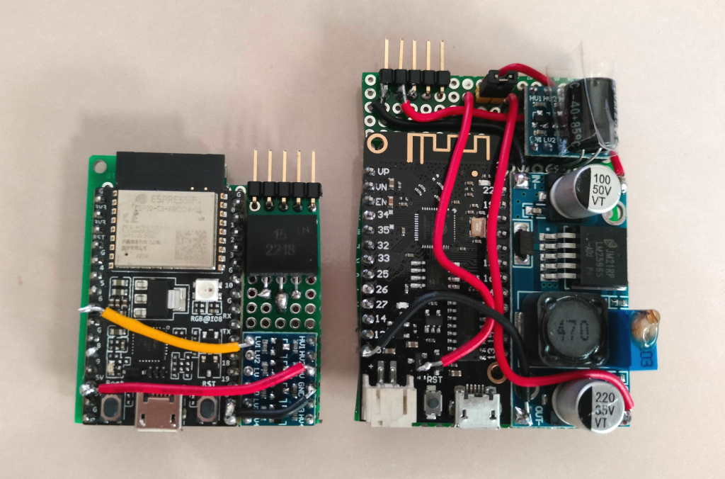
Here a couple of example boards:

Here's a smaller board with a Wemos S2 Mini:

Installation
- Flash the board with tasmota firmware for ESP32.
- Setup tasmota as per standard (wifi, mqtt etc)
- Edit this Berry script so that GPIO_RX and GPIO_TX match your setup
- Go to the file manager, upload the script and rename it "autoexec.be" to have it run at every reboot.
Usage
On tasmota, you'll be able to control the A/C unit with a JSON command like:
DaikinCtrl {"active":true, "mode":"COOL", "fan":"NIGHT", "temperature":20, "swingH":true, "swingV":false }
Also, two sensors will be exposed:
- Internal Temperature
- Outside Temperature
(your ESP board will also probably have an internal temperature sensor that will be exposed by Tasmota)
This software is based on the reverse engineering work of @maser777 and @relghuar at OpenEnergyMonitor.
Thanks to you and all the other hackers!