SimpleFOC DriveShield v1.2


This is an open-source low-cost BLDC driver boards in the form of a Arduino shield. It is a part of the SimpleFOC project. The board is the big brother of the SimpleFOCShield and is designed to drive motors with higher current requirements, up to 30Amps. The board is created with the same philosophy as the SimpleFOCShield - to be simple to use, low-cost, and open-source and fully compatible with the SimpleFOClibrary.
Additionally the aim of the board is to serve as a template project for the community to build their own motor drivers.
- The board is relatively simple and can be easily modified to fit different requirements.
- The board is designed in EasyEDA and all the fabrication files are available for download
Components
- DRV8320H gate driver
- Hardware configuration
- 3PWM
- Protections: undervoltage lockout, charge pump fault, MOSFET overcurrent, MOSFET short circuit, gate driver fault and overtemperature
- BSZ0904NSI mosfets
- Standard 3mm x 3mm footprint (can be easily exchanged)
- Max current 75A
- Max voltage 30V
- ACS712:
- 30Amps bidirectional
- In-line current sensing
Features
- Boards absolute max ratings
- Max current: 20A continuous (peak 30A - measured)
- Max input voltage: 30V
- Stackable: running 2 motors in the same time
- Encoder/Hall sensors interface: Integrated 3.3kΩ pullups (configurable)
- I2C interface: Integrated 4.7kΩ pullups (configurable)
- Configurable pinout: Hardware configuration - soldering connections
- Arduino headers: Arduino UNO, Arduino MEGA, STM32 Nucleo boards...
- Open Source:
- Fully designed in EasyEDA: EasyEDA project
- Fully available fabrication files - how to make it yourself
- Low-cost: Estimated price of 25-40€ - Will be available in the SimpleFOC shop
Shield version comparison
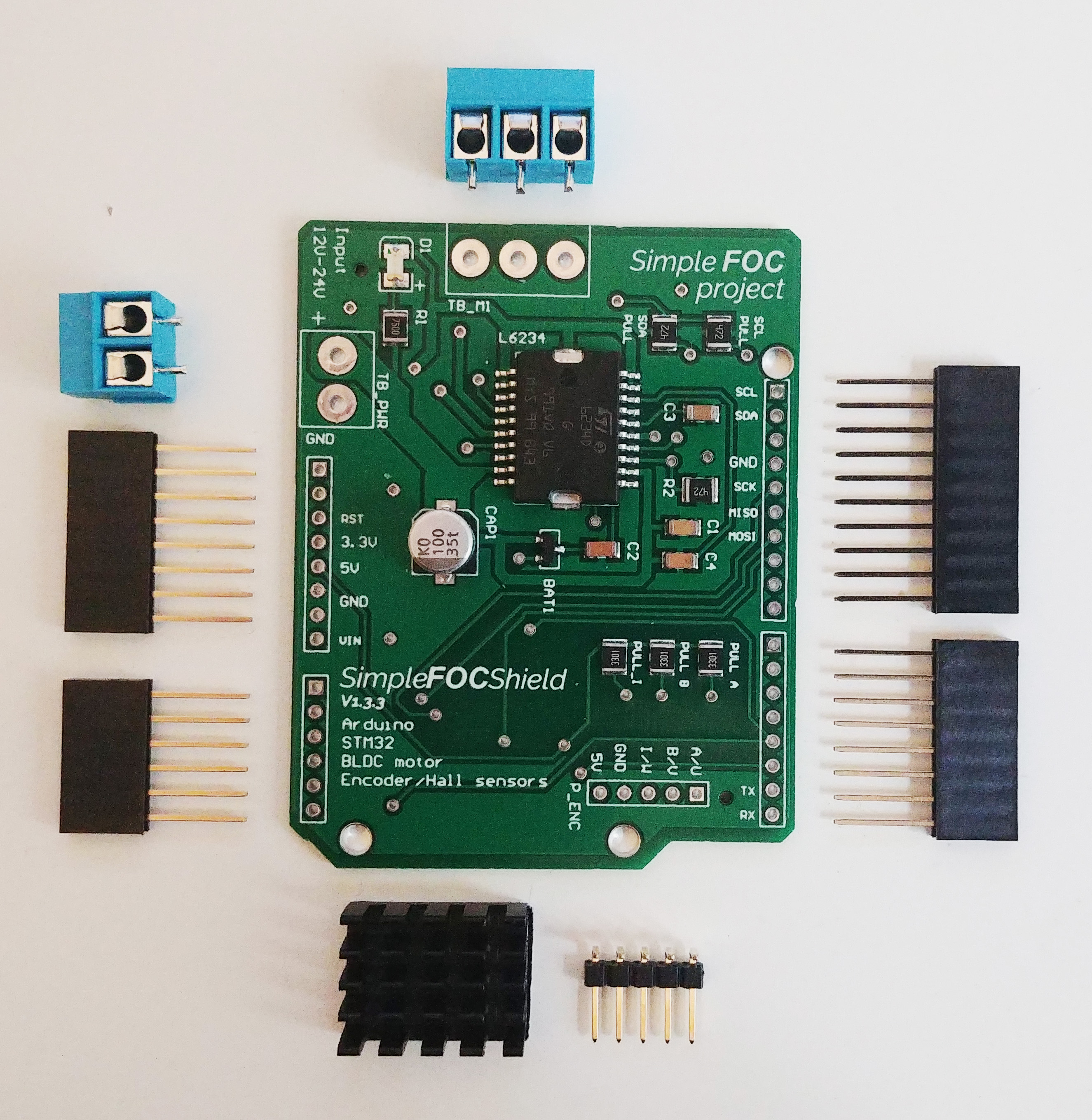
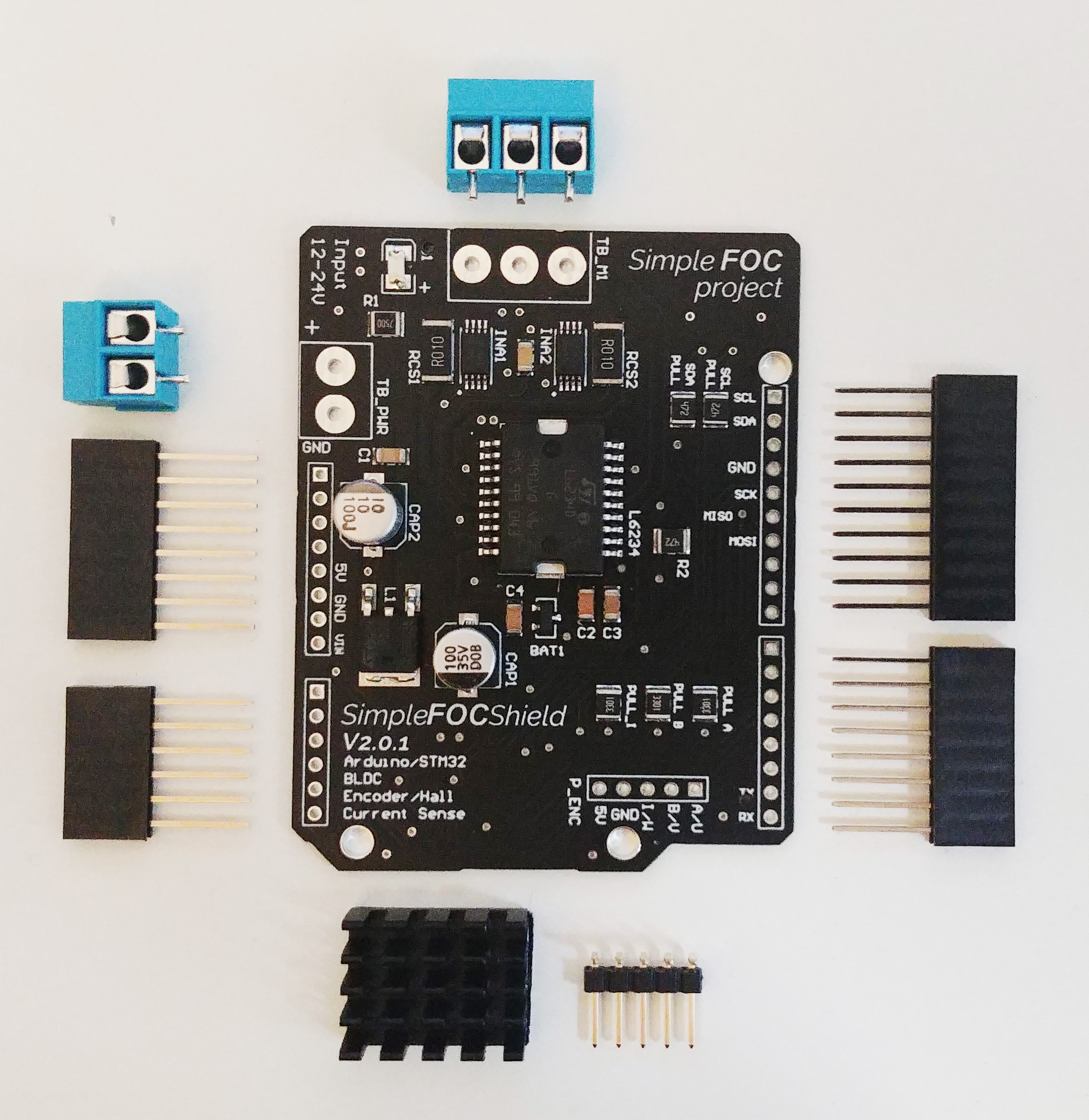
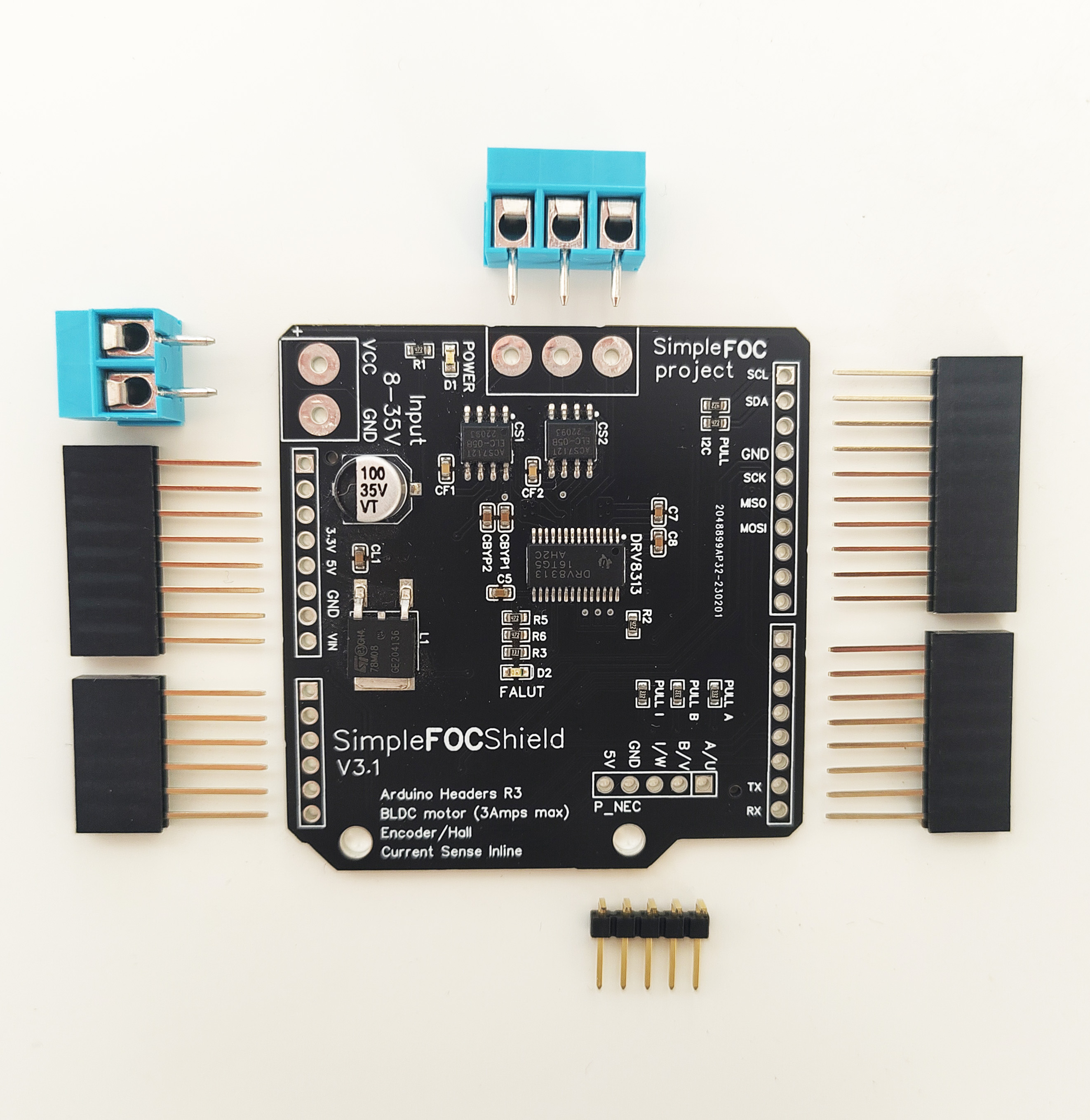
| Feature | SimpleFOCShield v1.x | SimpleFOCShield v2.x | SimpleFOCShield v3.x | SimpleFOC DriveShield v1.x |
|---|---|---|---|---|
 |
 |
 |
 |
|
| PWM Driver | L6234 | L6234 | DRV8313 | gate driver: DRV8320H mosfets: BSZ0904NSI |
| Current Sense | ❌ | INA240 | ACS712 (5A) | ACS712 (30A) |
| Current measurement range | ❌ | (configurable) ±3.3/5Amps | ±5Amps | ±30Amps |
| Onboard LDO | ❌ | LM7808 | LM7808 | ❌ |
| Stackable | ✔️ | ✔️ | ✔️ | ✔️ |
| Max current | 2Amps (5Amp peak) | 2Amps (5Amp peak) | 2Amps (3Amp peak) | 20Amps (30Amp peak) |
| Max voltage | 24V | 35V | 35V | 30V |
| Protections | Overtemperature | Overtemperature | Overtemperature, Overcurrent | undervoltage lockout, charge pump fault, MOSFET overcurrent, MOSFET short circuit, gate driver fault, overtemperature |
| Footprint | 68mm x 53 mm | 68mm x 53 mm | 56mm x 53mm | 56mm x 53mm |
| Design tool | Altium Designer 2019 | Altium Designer 2019 | EasyEDA | EasyEDA |
Board evolution timeline
To check the release timeline, click here
| Version | release | Release date | Comment |
|---|---|---|---|
| SimpleFOC DriveShield v1.0 | v0.1 | 05/24 | - Test version - DRV8300 gate driver - SE3082G dual mosfets - ACS712 (range +-30Amps) - 20V max voltage |
| SimpleFOC DriveShield v1.0 | v1.0 | 06/24 | - Transition to DRV8320H gate driver - 30V max voltage |
| SimpleFOC DriveShield v1.1 | v1.1 | 07/24 | - Transition to 3x3mm BSZ09x mosfets instead of SE3082G - 30V max voltage |
| SimpleFOC DriveShield v1.2 | v1.2 | 08/24 | Initial release - Transition to 4 layer PCB - Enabling stacking (soldering pads) - Configurable pullups (I2C and encoder) |
Size comparison with SimpleFOCShield v3

Temperature characteristics
This board can measure the phase currents up to 30Amps, so it is intended to be used in applications that require current draw up to around 20Amps continuous. For higher currents especially in the range of 15-30Amps the board can get quite hot. Depending on the copper thickness of the PCB chosen when ordering the board the temperature can vary, as well as the cooling conditions. The board can be fitted with a heatsink to improve the thermal performance.
So I've wanted to quantify the temperature characteristics of the board when a continuous current is applied to the motor. The measurements were done with a relatively constant ambient temperature of around 25°C. The board was powered with 24V. The motor was run at very low speed (0.1rad/s) in the open loop and the current (q component) was set to 10, 15 and 20 amps for prolonged periods of time. I've measured the temperature on the top of the board on the DRV8320H gate driver and the BSZ0904NSI mosfets. I've used the PICOLOG TC-08 thermocouple data logger to do the measuring.
Two copper thicknesses were tested
- Standard 4-layer:
- 1oz (35um) copper thickness on top and bottom layers,
- 0.5oz (17.5um) copper thickness on inner layers
.jpg)
.jpg)
- Thick 4-layer:
- 2oz (70um) copper thickness on top and bottom layers,
- 0.5oz (35um) copper thickness on inner layers
.jpg)
.jpg)
Experiment results
Here is the table of the results
| Current [A] | Standard 4-layer MOSFETS | Thick 4-layer MOSFETS | Standard 4-layer DRV8320 | Thick 4-layer DRV8320 |
|---|---|---|---|---|
| 10 | 57°C | 53°C | 50°C | 52°C |
| 15 | 78°C | 68°C | 62°C | 62°C |
| 20 | 125°C | 100°C | 82°C | 82°C |
So the results seem to suggest that, as the BSZ0904NSI mosfets are rated for temperatures up to 150°C and the DRV8320H gate driver up to 125°C, the board can be used up to 20Amps without additional cooling.
However, I would definitely recommend using a heatsink or a thicker copper PCB (2oz top and bottom layers) for currents above 15Amps continuous.
Measured temperatures during the experiment

