IBM-Wheelwriter-Hack
Turning an IBM Wheelwriter into a unique printer
Video:
This project has three goals:
- Electronically connect an Arduino to an IBM Wheelwriter 6 (will probably work for other models) to emulate the IBM printer option card when using a custom driver.
- Allow someone to type directly to the typewriter from a computer keyboard, through a computer.
- Add fun options, e.g., raster printing (!) at a low dpi through the use of micro-up/down and micro-backspace.
Background
The IBM Wheelwriter, circa 1984, is an electronic typewriter with a beautiful Model M keyboard and a daisy-wheel print head. The typewriter is (not suprisingly, given that it is an IBM) built like a tank, and the PCBs are exceedingly well laid out and annotated, and easy to access. The case pops off with a bit of elbow grease, and there is an expansion port on one of the two PCBs with labeled pins. Yay!
Technical Details
The only pins we really care about are "bus" and ground, although eventually we'll care about 5V when we attach the Arduino and want to power it from the typewriter itself.
Reverse-engineering the bus has been an interesting two-week endeavor. The tools necessary: an Arduino (I'm using a Light Blue Bean+ (Update on 17 Jan 2017: I have added code for an ATmega Arduino Nano) and a logic analyzer. The initial logic analyzer I used was a Bus Pirate, but unfortunately the BP does not have enough memory to capture some of the longer sequences of commands (e.g., a carriage return). So, a colleague loaned me a Saleae 8-pin logic analyzer, which has worked great (though it does have some quirks).
As of February 2017, I have successfully reverse engineered printing characters, carriage returns, fast printing of characters, print head forwards/backwards/up/down, etc. Here is the basic idea for sending a command on the bus:
-
Pulse period: 5.34us (I originally thought it was a 5.25us pulse, but after locating the 11.975MHz crystal on the PCB, I realized that 11.975MHz divided by 64 is 5.34us, which is most likely the actual period. In all of my testing I assumed it was 5.25us, and it worked fine.
-
Number of pulses sent per command: 10 (an "I'm writing to the bus" to begin, and nine more bits)
-
Normal state of the bus: high (5V), and devices sending commands must pull the bus to low for a zero, and leave high for a one.
-
The first pulse is always a throwaway 0, indicating that a device is going to write 9 more bits to the bus.
-
The next nine bits are (as far as I can tell) in LSB order. Commands seem to always start with 0b100100001 (which is sent right-most bit first). I originally thought the commands were MSB first, but when I was reverse engineering the carriage-return command the numbers came out such that it looks like it is LSB. This makes reading the logic traces in the reverse order from the numeric bit pattern. Maybe I should have kept the MSB ordering in the code because it is easier for humans to read, but I switched it to make it consistent with the way the typewriter expects commands.
-
When a device sends its 10 bits on the bus, there is almost always a response from the motor driver PCB (that's what I'm calling it), and this response is usually a 10-byte zero (a 53.4us zero pulse, basically). We need to look for this response before sending the next 10-bit value in our command.
-
The reason I am somewhat hesitant to declare the MSB/LSB debate finished is because the character table is completely whacky. It is not ASCII, and it isn't any of the EBCDIC variations I've tracked down. You might think that there would be some method to it, but I haven't yet figured it out. The table below is what I have so far; as you can see, the characters A, B, C have character codes 0x20, 0x12, and 0x1b. I have a feeling that the codes might be based off of the keyboard scan codes, but I haven't found the pattern yet.
-
The following is the Arduino array mapping ASCII to the characters the printer expects. I haven't figured out what encoding the typewriter expects, and capturing this data was an exercise in patience and a lot of "type a key, look at the bit pattern" (which I automated to every extent possible!). Note: this is the mapping for the Prestige Elite 12P daisy wheel -- I will eventually get a Courier printwheel to see what characters need to be modified (e.g., there are no curly braces in the Prestige Elite font).
int asciiTrans[128] =
//col: 0     1     2     3     4     5     6     7     8     9     a     b     c     d     e     f     row:
    {0x00, 0x00, 0x00, 0x00, 0x00, 0x00, 0x00, 0x00, 0x00, 0x00, 0x00, 0x00, 0x00, 0x00, 0x00, 0x00, // 0

//
     0x00, 0x00, 0x00, 0x00, 0x00, 0x00, 0x00, 0x00, 0x00, 0x00, 0x00, 0x00, 0x00, 0x00, 0x00, 0x00, // 1

//    sp     !     "     #     $     %     &     '     (     )     *     +     ,     -     .     /
     0x00, 0x49, 0x4b, 0x38, 0x37, 0x39, 0x3f, 0x4c, 0x23, 0x16, 0x36, 0x3b, 0xc, 0x0e, 0x57, 0x28, // 2

//     0     1     2     3     4     5     6     7     8     9     :     ;     <     =     >     ?
     0x30, 0x2e, 0x2f, 0x2c, 0x32, 0x31, 0x33, 0x35, 0x34, 0x2a ,0x4e, 0x50, 0x00, 0x4d, 0x00, 0x4a, // 3

//     @     A     B     C     D     E     F     G     H     I     J     K     L     M     N     O
     0x3d, 0x20, 0x12, 0x1b, 0x1d, 0x1e, 0x11, 0x0f, 0x14, 0x1F, 0x21, 0x2b, 0x18, 0x24, 0x1a, 0x22, // 4

//     P     Q     R     S     T     U     V     W     X     Y     Z     [     \     ]     ^     _
     0x15, 0x3e, 0x17, 0x19, 0x1c, 0x10, 0x0d, 0x29, 0x2d, 0x26, 0x13, 0x41, 0x00, 0x40, 0x00, 0x4f, // 5

//     `     a     b     c     d     e     f     g     h     i     j     k     l     m     n     o
     0x00, 0x01, 0x59, 0x05, 0x07, 0x60, 0x0a, 0x5a, 0x08, 0x5d, 0x56, 0x0b, 0x09, 0x04, 0x02, 0x5f, // 6

//     p     q     r     s     t     u     v     w     x     y     z     {     |     }     ~    DEL
     0x5c, 0x52, 0x03, 0x06, 0x5e, 0x5b, 0x53, 0x55, 0x51, 0x58, 0x54, 0x00, 0x00, 0x00, 0x00, 0x00}; // 7
To send commands to the typewriter, we connect one pin of the Arduino to the bus through a MOSFET transistor (see the breadboard layout below, or the schematic in the KiCad files). When we set this pin high, the bus is pulled low, indicating a zero that we want to send. We capture other devices commands with a different Arduino pin that reads the raw state of the bus.
The hardest part about making the commands work is that there isn't a clock on the bus, and all commands must be timed for as close to 5.34us pulses as we can get. The Arduino is just barely fast enough to do this, and you have to resort to directly writing to the PORTD (or PORTB) pin registers and reading from the PIND (or PINB) registers to hit the tolerances. I.e., you can't use digitalWrite() or digitalRead() -- the commands are just too slow. The highest granularity timer we have access to on the Arduino (without going super-duper low-level) is delayMicroseconds(), which can come close enough to 5.34us to work, but it takes a bit of fiddling to get right. I will eventually port the code to an Arduino proper, but on the Light Blue Bean+, the tolerances don't have any wiggle room. Side note: the LBB+ has some internal ports rearranged, so PORTD and PORTB do not map to the standard Arduino pins. I've noted that in the code where necessary, and the code for the Arduino Nano has slightly different pins: pin 2 is the bus trigger through the MOSFET, and pin 3 is the bus input. Pin 4 is currently used as a button for testing.
Graphics
This has been one of the most fun parts of the project. I realized early on during my analysis of the signals coming from the bus that the typewriter has the ability to advance the print head in very small increments, both horizontally and vertically. This led to the idea that I could basically turn the typewriter into a slow, low-resolution dot-matrix printer by utilizing the period key as a pixel, and printing out runs of dots and spaces to form images.
My initial attempts involved simply breaking an image down into a grid of black-and-white pixels, and then sending each black pixel as a period, and each white pixel as a space. This worked, but was exceedingly slow (as you can imagine). For the second iteration, I re-wrote the encoding algorithm to accept a run-length-encoded string of periods and spaces, allowing me to fast-print the runs, which sped up the process considerbly. In the current iteration, I have updated the Arduino code to print runs of periods (as before), but also to simply advance the print head an equivalent number of spaces for whitespace, instead of individually advancing one space at a time (which sounded cool, but was slow...)
At this point, the graphics printing code on the Arduino is stable, but I'm still trying to figure out the best way to scale images so they make sense in black and white when printed at (roughly) 50-dots per inch. As I write more of the front-end software, I imagine I will re-invent the wheel some more and land on a reasonable method.
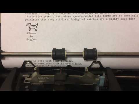
Here is an example of what the graphics looks like:

Bold, underline, and other non-standard functions
Interstingly, the Wheelwriter 6 that I have does not have bold functionality, though it does have a built-in underline function. Not suprisingly, an underline is as simple as writing a character then immediately writing the underline character, before advancing the print head. I have manually implemented this instead of attempting to turn on the built-in underline functionality.
Bold is a bit more interesting: because this model does not have a bold function, I had to play around with what bold should look like. It turns out that the best bold I have been able to create works like this:
- print a character
- advance the print head one micro-space
- reprint the character
- advance the print head a full character space less one microspace (to keep the spacing intact).
I think the bold looks great. :)
If anyone has any ideas on how to get the daisy wheel to print at an angle, let me know so I can implement italics. (/joke)
For the sendToNano.py program, I have included a parser that
looks for "**" (bold) and "__" (underline) Markdown and sends the appropriate commands
to the typewriter to format text in this fashion.
Here is a picture of the output with formatted text:

Breadboard Layout
The circuit used to connect the typewriter to an Arduino is extremely simple.

Nano Shield PCB
See the KiCad files for full schematic (hardware/Arduino_NanoShield folder) of a Nano shield, or order the part directly from OSH Park (under $6 for three copies):
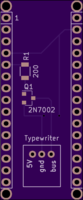
(Note: you will need two surface-mount components for the shield: a 200Ω 1206 resistor ($0.10 at Digikey) (and anything in the 200Ω range should work), and an n-channel MOSFET (2N7002 works fine) in an SOT-23 package, ($0.14 at Digikey)). If you want a proper connector for the typewriter interface, you can get one, too ($0.56 at DigiKey)
Note: you do not need to connect the 5V to the typewriter (indeed, do not, or you risk electrical issues); I put that onto the board in case someone did not want to connect the Arduino through USB. But, USB is how the computer controls the typewriter, so it will be connected...
Of course, you also need to be able to solder surface mount components.