Plant watering via BLE
This is the final project in the Advanced Computer Systems course (IOT) in Tel-Aviv University. by Omer Bracha & Yuval Ailer
Special thanks to:
- Prof. Sivan Toledo - Course lecturer and project guide.
- Netafim company - Donation of the gear needed to enable this project.
- Dov Ailer - Electrical Engineering guidance and support.
Example video:

Objectives
The purpose of the project is to create a plant watering system manageable by a Bluetooth connection. Due to the nature of battery enabled watering systems, the system needs to preform a high voltage operation (opening and closing the tap) for a short period of time, and for most of the day to remain inactive and preserve battery power. For this reason we chose to use the TI CC1350 low-power micro-controller. The following documentation will provide the needed information to recreate our project and use it on your own.
Getting Started
The project demands work on three levels:
- Android app for controlling the system (code provided).
- TI CC1350 on-board development (code provided).
- Build an electrical circuit (sketch and hardware list provided).
List of materials:
Hardware:
| Gear | Info | More |
|---|---|---|
| TI CC1350 Launchpad | Launchpad |
 |
| Android enabled device | Preferably version 27 |  |
| 2 X Resistors | 410 Ohm |
 |
| 2 X Relays | 5V enabled, can transfer up to 12V, 1A. we used: M45h | |
| Battery | Standard 9V | 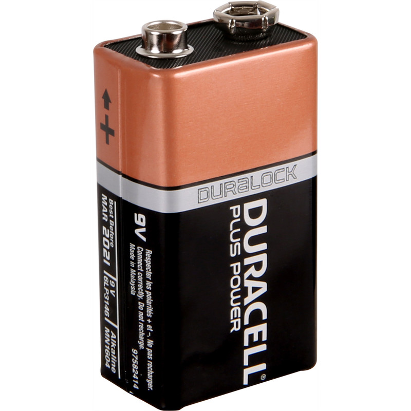 |
| 2 X Transistors | NPN, we used: 2n2222A |
|
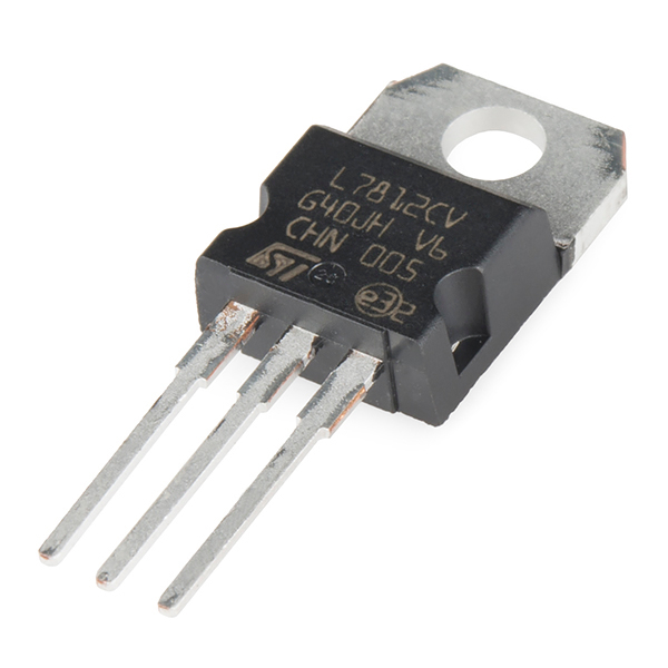
| Voltage Regulator | From 9V to 5V. we used L7805CV |
 |
| Soil moisture sensor | We used the Sparkfun one | 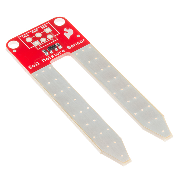 |
| Breadboard | If wanted, a soldering board |  |
| Wires | Different colors and lengths |  |
| Electric tap | We used the Netafim Aqua-Pro that was generously donated to us by the company |  |
Software:
- Android studio - for creating and editing Android apps
- TI Code composer studio - for developing software on the CC1350
- TI Sensor controller studio - to test and verify the soil moisture sensor
Developing process
Android application:
We used Android Studio 3.0.1 for developing the application.
For implementing a BLE application we were assisted by this example, And this manual.
We changed the Read / Write functions in the following manner: We used the write function to open and close the tap, and the read function to receive information from the soil moisture sensor.
Using the application:
-
After opening the application, a connection window will appear, with available BLE devices. Find the TI-RTOS board by the name SimpleBlePeripheral.
-
After pressing on it, the application will connect to the board and open a window with three buttons – Open tap, Close tap, Read humidity. When pressing the open / close tap buttons, the application will write to the board via BLE, and the board will then open / close the tap.
-
When pressing the Read humidity button – the application will read information from the soil moisture sensor, and will show one of the three messages:
-
- If the moisture is too low – "Please water me!".
-
- If the moisture it too high – "I'm flooding! Stop the water!".
-
- If the moisture is just right – "I feel sooo good!".
- Upon reading these messages, the user will know if needed to open, close, or do nothing with the tap.
About the process:
First of all, this was our first time dealing with an android application, so we spent some time learning the Android studio software and implementing some basic apps.
After that, using the example and the manual that were mentioned above, we built the write functions that open and close the tap using different characters to represent each action and transmitting them over BLE.
Finally, we added the read function that receives data from the soil moisture sensor, going through the TI-RTOS board and transmitted via BLE to the app, and according to the character transmitted shows a different message upon the screen.
TI-RTOS application:
We used Code Composer Studio 7.3.0 for developing the application running on the board.
For implementing the TI-RTOS application, we were assisted by two examples from the SimpleLink SDK: adcsinglechannel and simple_peripheral.
For the BLE connection, we used the simple_peripheral example.
We adjusted the write function to send 200ms signals to the data outputs (DIO12, DIO15) of the board, in order to open and close the tap when receiving the command from the board via BLE.
The read function was adjusted based on the adcsinglechannel example to read data from the soil moisture sensor (DIO23) and send characters over BLE to the mobile application (sending "3" represents low moisture, "4" represents good moisture, and "7" represents too much moisture).
About the process:
In HW5, we learned how to use the BLE protocol to read and write to the TI-RTOS board using the simple_peripheral example. We used this example to try and write characters that will send signals through the different data outputs of the board, and for the first stage turn on / off LEDs.
After completing that, we connected the data outputs of our choice (DIO12, DIO15) to the electrical circuit that will open and close the tap (further explanations regarding how the electric circuit works will be discussed below).
We then were assisted with the adcsinglechannel example to read data from the soil moisture sensor. We used the Sensor Controller Studio software to learn about the values returned from the sensor, and then again used LEDs connected to the board to understand the different levels that we reach in different moisture situations (putting the sensor in the air, in dry soil, wet soil and in a glass of water). After understanding that, we adjusted the read function in the code to read data from the sensor, and then send characters representing each level of moisture to the mobile app via BLE.
Electric board:
We used the following circuit design to implement the physical open/close operations in the tap activated by the signals from the CC1350 DIO outputs.
Circuit design:

- As can be seen in the design, a 9v battery powers the circuit, and eventually powers the DC motor that opens and closes the tap.
- The 9v voltage is reduced to 5v using a voltage regulator. the 5v is connected to the coils of the relays.
- Diodes were connected in parrallel to the coils in order to protect the circuit.
- The other end of the coil is connected to the transistor.
- When a signal from the CC1350 is received (via the resistor) , it opens the transistor to flow current from the coil to the battery minus.
- This will change the state of the relay and will connect the 9v to the DC motor thus opening/closing the tap.
About the process:
At first, we had only knowledge that the TI-TROS can output a maximum of 5v through the data outputs, with no knowledge of the current provided by them. We spoke on the phone with Esteban Socolsky from Netafim, and asked him about the tap. He told us that in order to open the tap, we will need to send a pulse of 9v, 0.5 mA current for 200 milliseconds, and to close - a pulse of -9v.
With this new knowledge, we understood that we need to build a slightly more sophisticated circuit in order to make the tap open/close through the board. We consulted with Professor Sivan Toledo (our course lecturer) and Dov Ailer (Electrical engineer by profession). We made our conclusions, and tried to implement their advices. At first, we tried to work with a relay in order to meet the demands of the tap. We connected a 9v battery to the relay and upon activating the coil with a 5v power source the 9v would pass through and open/close the tap as expected.
Next, we tried to trade the 5v power source with an output from the board, but that did not give us enough power to activate the coil. We understood that the way to operate the circuit correctly is to add a NPN BJT transistor (operating as a switch) that will be connected in the following way: Emitter connected to the ground, Collector to the negative side of the coil and the base connected through a resistor to the data output of the board. Now, given a pulse from the board, the transistor will be activated, current will flow between collector and emitter and the coil will be activated.
In order to achieve the 5v power source to connect to the positive side of the coil in the relay, we used a voltage regulator that with input of 9v from the battery, gave us a 5v output.
After succeeding with that, we built an almost identical circuit for closing the tap, but the 9v-ground outputs of the relay that are connected to the tap were connected the other way around. This way, at each time only one relay will be working and we can generate opposite pulses for opening and closing the tap.
We also used the 5v output from the regulator to power the TI-RTOS board.
How to start using this project:
The process involves using the previously mentioned software and assuming the electrical circuit is ready and connected properly.
First of all - Download this project or clone it using git command:
git clone https://github.com/yuvalailer/plant-watering-via-BLE.git
To start the android application:
- Download and install Android studio.
- Open the project in the Android studio.
- Get your android device ready for USB debugging.
- Build and debug the app on the device.
To start the TI-RTOS application:
- Download and install Code Composer Studio.
- Open the code in CSS.
- Connect the board to the computer.
- First compile and debug the stack example.
- Then compile and debug the app example.
Merge:
- Once the board powered on, the Android application will recognize the board under the name SimpleBlePeripheral.
- Once connected, use the buttons to control the tap.