DIY Water Leakage Sensor For Home Assistant...
Or any MQTT based system
About
This article accompanies the "DIY Water Leakage Sensor" YouTube series.
It contains the code, libraries, diagrams, 3D print files and more information that I promised in the videos:

BUY VS BUILD
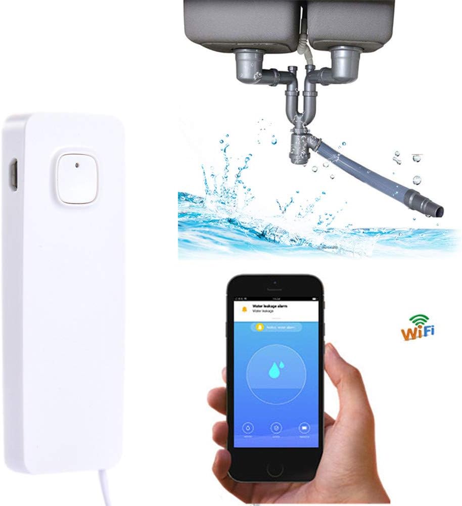
You can always go ahead and buy a ready-to-use a solution like this CONNECTIFY Smart Water Leakage Sensor but these devices usually would only work with their respective apps, and some of them would require you to pay extra in order to receive push notifications. Now, this article and its video provide a step-by-step guide and links to everything you need to build the same device for 3x cheaper than the cheapest option available.
In addition to detecting water leakage and sending notifications. This device:
- Goes to deep sleep and only wakes up every 30sec (configurable) to save energy
- When water is detected, only then, the connection to WiFi is made, again, to save energy
- Has a removable LiPo battery for easy of charge
- Clever wiring of the water sensor to extend its life expectancy (more details in the wiring section)
- Sends notifications (and any type of data) to an MQTT topic, enlarging the possibilities of what you can do with the data
In my case, I will be sending the notifications to my Home Assistant setup in order to trigger a pre-defined automation that:
- Pushes actionable notifications to our phone devices through Home Assistant companion apps
- Converts notification alarm to a text (Alexa TTS capabilities) and play it through the Amazon Echo devices around the house
- And just in case we managed to miss these, it turns the kitchen LED light to RED informing us of an emergency
- Repeats every 5min until someone explicitly acknowledged the issue.
The beauty of this is I can decide to trigger any type of notifications in the future such as playing an alarm sound or sending SMS notifications...
So without further ado, let's start with a list of all hardware components, Apps and Libraries I've used in this project:
⚡️ COMPONENTS AND SUPPLIES
- WEMOS D1 R2 (ESP8266 ESP-12F)
- Water Level Sensor
- 5 LiPo Batteries And Charger
- Spade 2P Cable Lead Plug
- Solder Kit
- Helping Hands for soldering
- Screwdriver Set
- Breadboard - Jumper Wires - Male to Male Jumper Wires + Tweezer
🖥 APPS
📦 Libraries
Hardware Overview: Water Sensor

This Water Level Sensor Module has a series of ten exposed copper traces, five of which are power traces and five are sense traces. These traces are interlaced so that there is one sense trace between every two power traces. Usually these traces are not connected but are bridged by water when submerged
The working of the water level sensor is pretty straightforward: The series of exposed parallel conductors, together acts as a variable resistor (just like a potentiometer) whose resistance varies according to the water level. The change in resistance corresponds to the distance from the top of the sensor to the surface of the water.
The resistance is inversely proportional to the height of the water:
- The more water the sensor is immersed in, results in better conductivity and will result in a lower resistance.
- The less water the sensor is immersed in, results in poor conductivity and will result in a higher resistance.
The sensor produces an output voltage according to the resistance, which by measuring we can determine the water level.
Hardware Overview: WEMOS R1 D2
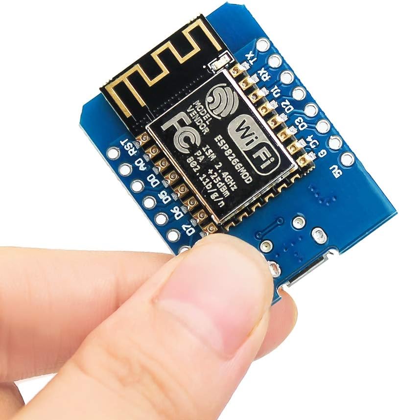
I've decided to use the WEMOS R1 D2 microchip for this project because it has a small size that saves space and can easily fit in a printable 3D case, but also because of a few reasons:
- It has an Analog pin
- It has WiFi capabilities
- It supports OTA online: Updating code Over-The-Air
- 4MB of memory which more than enough for our needs
- And because it's compatible with Arduino IDE, making the programming easy
THE WIRING
The wiring is pretty straightforward. Please follow the diagram bellow. Also, here are some notes that might help you figure it out:
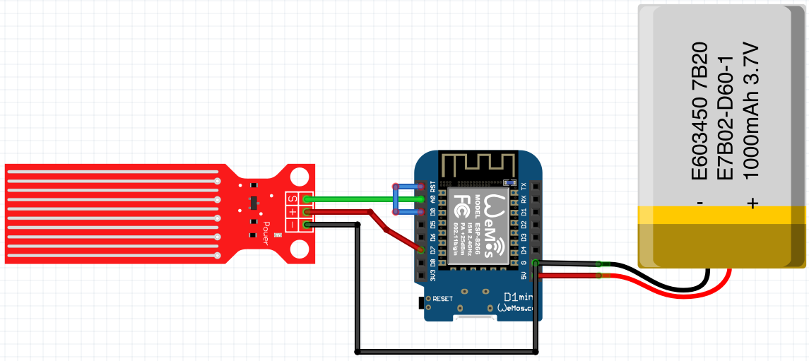
- Blue wire connecting RST and D0: Required to allow the WEMOS board to go to sleep.
- Red wire connecting water sensor to D7: You might be wondering why the water sensor is not directly connected to the 3v3 pin. Well, one commonly known issue with these sensors is their short lifespan when exposed to a moist environment. Having power applied to the probe constantly speeds the rate of corrosion significantly. To overcome this, I recommend that you do not power the sensor constantly, but power it only when you take the readings. An easy way to accomplish this is to connect the VCC pin to a digital pin of an Arduino and set it to HIGH or LOW as per requirement. So, we'll connect the VCC pin to the digital pin #7 of an Arduino.
Wiring source files are included under wiring folder
3D PRINTED CASE
No one likes wires hanging around, and so I included the source and STL files for the 3D case I prepared for this project. All of it is under 3d folder folder and you can do whatever the heck you want with it.
THE CODE
The code within main.cpp file is well documented, but I'll try to explain the concepts and ideas behind the code in this section. But first of all, copy the file secrets_copy.h to secrets.h and edit its content with your details: WiFi credentials, Home Assistant details...
The sketch begins with the creation of a few objects we'll need along the way: Ticker that calls repeating actions and which we will use to put the board to sleep and then wake up. WiFiClient that we use to connect to Wifi and PubSubClient that we use to send data through MQTT
Ticker ticker;
WiFiClient espClient;
PubSubClient client(espClient);
Then we declare a few variables like the Arduino pins for the sensor reading and power, as long as the sleep duration and number of tries we aim to do while connecting to WiFi because we want to avoid draining the battery trying to connect to WiFi indefinitely.
#define sensorPower D7 // Power pin
#define sensorPin A0 // Analog Sensor pins
#define durationSleep 30 // seconds
#define NB_TRYWIFI 20 // WiFi connection retries
As you might have noticed, there is no loop() function in this sketch, only a setup() function, and that's because instead of executing some commands in a loop fashion like most Arduino projects, this board is programmed to go to sleep until its wake up moment arrives, in which case, it will executing everything until setup() function before going back to sleep again. Here is how it's programmed:
void setup()
{
    // only print debug messages to serial if we're in debug mode
    if (DEBUG == true) {
        Serial.print("Waking up ");
    }

    // Step 1: Set D7 pin as an output pin ready to receive power
    pinMode(sensorPower, OUTPUT); // Set D7 as an OUTPUT
    digitalWrite(sensorPower, LOW);

    ...

    // Step 2: Wake the sensor up & get a reading
    int waterLevel = readSensor();

    ...

    // Step 3: If water is detected then
    if (waterLevel > 1) {
        connectToWiFi(); // 1- connect to WiFi
        connectToHass(); // 2- connect to Home Assistant MQTT broker
        publishAlarmToHass(waterLevel); // 3- publish the water level on the MQTT topic
    }

    // Step 4: Go back to sleep for the next 30 sec
    ESP.deepSleep(durationSleep * 1000000);

}
The function that reads the water level is straightforward and well documented as well:
int readSensor()
{
    // Step 1 : Turn the sensor ON by providing power to D7 pin
    digitalWrite(sensorPower, HIGH);
    // Step 2 : Wait for a just little bit
    delay(10);
    // Step 3 : Perform the reading
    sensorData = analogRead(sensorPin);

    // Step 4 : Turn the sensor OFF
    digitalWrite(sensorPower, LOW);

  return sensorData;
}
Finally
All contribution to this project is appreciated