Check last release with binaries distribution for Windows and Linux platforms here :
https://github.com/TheKikGen/stm32-tkg-hid-bootloader/releases

STM32F10x TKG-HID-BOOTLOADER
This is a HID (Human Interface Device) driverless booloader for the STM32F10x family line, including the famous Bluepill. It was inspired by the original project from bootsector, but also from the derivated HID Bootloader from Vassilis Serasidis.
However this bootloader is not compatible anymore due to a lot of enhancements, code optimizations and bug corrections.
The bootloader supports transparently low-medium and high density devices without recompilation. The tkg-hid-bootloader doesn't use any ST libraries, but only CMSIS SDK. So, its size is under 4 Kbytes (2 high density pages), allowing more space for user programs (user flash memory starts at 0x08001000).
It was not possible (reasonable) to keep the size under the 2K ( 1 HD flash page) because before jumping to the user application, the bootloader must ensure that the current state of the MCU is correctly initialized. Depending on your own hardware, and GPIO settings, that size can vary, and we can't change everytime the "rom start" address in the linking process. So 4K is a good compromize between size and code quality, and will let room for new enhancements.
The TKG-FLASH has many new features, like info, dump, simulation mode, progression bar,compatibilty with the STM32DUINO platform, and can be easily integrated in the Arduino IDE
Since version 3.10, a xor checksum control is done at the end of the flashing process.
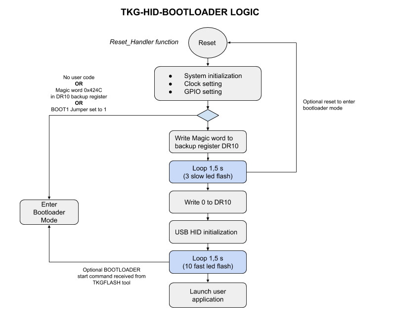
Entering the bootloader
- "Double push" on the reset button
- "DTR reset" method when flashing with TKG-FLASH if the right com port is given to toggle DTR (not always reliable)
- BOOT1 set to HIGH (permanent with jumper set fro ultimate case !)
- Writing the value 0x424C in the DR10 backup register (ex : from your own firmware before rebooting)
- A START command from TKG-Flash tool
TKG-FLASH 3.1
+-----------------------------------------------------------------------+
|             TKG-Flash v3.1 STM32F103 HID Bootloader Flash Tool        |
|                     High density device support.                      |
|       (c) 2020 - The KikGen Labs     https://github.com/TheKikGen     |
+-----------------------------------------------------------------------+
Build : 3.210120.1702

  Usage: tkg-flash <firmware file name> [<options>]
         tkg-flash -info

  Options are :
  -info         : get only some information from the MCU without flashing.

  Flashing options :
  -d=16 -d=32   : hexa dump sectors by 16 or 32 bytes line length.
  -ide          : ide embedded, no progression bar, basic info.
  -o=<n>        : offset the default flash start page of 1-255 page(s)
  -p=<com port> : serial com port used to toggle DTR for MCU reset.
  -sim          : flashing simulation.
  -w=<time s>   : HID device waiting time (10s default).

  Examples :
  tkg-flash myfirmare.bin -p=COM4 -w=30
  tkg-flash myfirmare.bin -d=16 -s
The TKG-FLASH tool has the following features :
- "DTR reset" capability if a com port is passed in the command line with the "-p" option
- "embedded" mode, less verbose, when tkg-flash must be integrated in the Arduino IDE (see below).
- Waiting time parameter to adjust the waiting time for toggling DTR serial port and HID device to be ready (10s default)
- Flashing simulation allowing the exact same behaviour but without writing the firmware to the flash memory
- Dump firmware file feature
- Page offset parameter to change the jump address.
The page offset allows you to flash a firmware that was not linked with the tkg-hid-bootloader FLASH_BASE_ADDRESS at 0x08001000. For example, a firmware compiled with the stm32duino bootloader upload method will be linked with a base address at 0x08002000. So to make the bootloader to load that firmware at the right address, you can offset of 2 pages for a high density device (2048 * 2 = 0x1000 bytes per pages), or 4 for a medium density one ( 4 x 1024 = 0x1000 bytes par page).
Examples :
To flash myfirmware.bin under windows, using COM1 DTR as reset method :
tkg-flash myfirmware.bin -p=COM1To do the same under Linux, with an offset of 2 pages :
tkg-flash myfirmware.bin -p=ttyACM0s -o=2To get informations from a device in bootloader mode :
# tkf-flash -info

+-----------------------------------------------------------------------+
|             TKG-Flash v3.1 STM32F103 HID Bootloader Flash Tool        |
|                     High density device support.                      |
|       (c) 2020 - The KikGen Labs     https://github.com/TheKikGen     |
+-----------------------------------------------------------------------+
Build : 3.210120.1702

> Searching for [1209:BEBA] HID device...|
> [1209:BEBA] HID device found !
  INFO - Informations reported by the bootloader :
      Firmware version       : 0310
      MCU Flash memory size  : 128 K (medium density device)
      Page size              : 1024 bytes
      Page offset            : 4 pages
      Flash base address     : 0x08001000
  Bootloader mode still active.
> TKG-Flash end.
How to upgrade from your current bootoader
A special stm32duino sketch project can be found at https://github.com/TheKikGen/stm32-tkg-hid-bootloader/tree/master/tools/tkg_hid_btl_uploader
-
Load the project in the Arduino IDE
-
Specify the right uploading method in th "tools" menu, corresponding to your current bootloader
-
uncomment one of the target in the .ino source. Usually for a Bluepill STM32F103C you will choose GENERIC_PC13.
// --- TARGETS --- #define GENERIC_PC13 //#define MIDITECH_MIDIFACE //#define MIDIPLUS_SMART_PAD -
The flash operation will start and the new bootloader will be written at 0x08000000.
-
You can open a serial terminal to get a small report and check eventual error messages.
STM32F1 TKGL HID BOOTLOADER UPGRADE BY THE KIGEN LABS HID Bootloader size is 3044 bytes. Upgrading............ 3044 bytes written. Bootloader flashed. Please reset the board. -
"Double click" reset button to go directly in bootloader mode and flash your own firmware with tkg-flash
-
You can use "tkg-flash -info" to check the current bootloader firmware.
-
You can also use CTRL + ALT + S within the Arduino IDE to get a binary in the tkg_hid_btl_uploader directory.
Arduino IDE integration
Quit Arduino IDE if active.
First, to add a new upload method in the STM32F1 boards, you need to modify the "boards.txt" usally located in your Arduino installation directory at "Arduino\hardware\Arduino_STM32\STM32F1". Make a backup copy before editing the file :
Search the section "## Generic STM32F103C ##" in the board.txt file, then the sub section "#-- UPLOAD METHODS --", and add the following lines at the last part of the upload section, to create a new "TKG-HID" upload method that will be shown in the IDE menu :
genericSTM32F103C.menu.upload_method.TKG-HIDUploadMethod=TKG HID bootloader 3.1
genericSTM32F103C.menu.upload_method.TKG-HIDUploadMethod.upload.tool=tkg_hid_upload
genericSTM32F103C.menu.upload_method.TKG-HIDUploadMethod.build.upload_flags=-DSERIAL_USB -DGENERIC_BOOTLOADER
genericSTM32F103C.menu.upload_method.TKG-HIDUploadMethod.build.vect=VECT_TAB_ADDR=0x8001000
genericSTM32F103C.menu.upload_method.TKG-HIDUploadMethod.build.ldscript=ld/tkg_hid_bootloader.ld
Save and close boards.txt file.
Create now a new linker script file for your board, as mentioned in the above upload method, named "tkg_hid_bootloader.ld" in the directory STM32F1/variants/generic_stm32f103c/ld/ , and copy paste the following content :
/*
 * TKG-HID FLASH BUILD LINKER SCRIPT - V3.1
 * STM32F103C8 / STM32F103CB
 */
MEMORY
{
  /* Real RAM size of the board */
  ram (rwx) : ORIGIN = 0x20000000, LENGTH = 20K
  /* Flash RAM size of the board minus 4K */
  rom (rx)  : ORIGIN = 0x08001000, LENGTH = 124K
}

/* Provide memory region aliases for common.inc */
REGION_ALIAS("REGION_TEXT", rom);
REGION_ALIAS("REGION_DATA", ram);
REGION_ALIAS("REGION_BSS", ram);
REGION_ALIAS("REGION_RODATA", rom);

/* Let common.inc handle the real work. */
INCLUDE common.inc
The ram and rom origin and lengths are adjusted to match the uC/board specifications.
- Ram origin starts at 0x20000000. The length is the RAM size of your MCU (20K for the STM32103C8/CB).
- Program origin in rom starts at 0x08000000 + TKG bootloader size (4K = 0x1000). The LENGTH is the flash memory size of the MCU minus 4k (bootloader size).
You must then add a new upload method in Arduino/hardware/Arduino_STM32/STM32F1/platform.txt (make a backup copy before editing the file) in the "# Uploader tools
" section :
# TKG-HID upload 3.1
tools.tkg_hid_upload.cmd=tkg-flash
tools.tkg_hid_upload.cmd.windows=tkg-flash.exe
tools.tkg_hid_upload.cmd.macosx=tkg-flash
tools.tkg_hid_upload.path={runtime.hardware.path}/tools/win
tools.tkg_hid_upload.path.macosx={runtime.hardware.path}/tools/macosx
tools.tkg_hid_upload.path.linux={runtime.hardware.path}/tools/linux
tools.tkg_hid_upload.path.linux64={runtime.hardware.path}/tools/linux64
tools.tkg_hid_upload.upload.params.verbose=-d
tools.tkg_hid_upload.upload.params.quiet=n
tools.tkg_hid_upload.upload.pattern="{path}/{cmd}" "{build.path}/{build.project_name}.bin" -p={serial.port.file} -w=15 -ide
and copy the tkg-flash tool in the Arduino\hardware\Arduino_STM32\tool(your platform).
Under Linux, and Mac-OSX, you probaly need to :
-
chown +x the tkg-flash binary
-
add a rules in /etc/udev/rules.d/ to allow the Arduino IDE to see the HID device, containing the follwing line :
SUBSYSTEMS=="usb", ATTRS{idVendor}=="1209", ATTRS{idProduct}=="beba", MODE:="0666"
-
Unplug your device, and restart udev administration service with a "sudo udevadm control --reload-rules " command line
You need to restart the Arduino IDE to see your changes.
Make an Arduino application to reboot in bootloader mode
When the board is booting, the bootloader checks the value 0x424C in the DR10 backup register to eventually enter in bootloader mode. To write this value from your own application, you can use the following example:
 #define BOOT_BTL_REGISTER     DR10
///////////////////////////////////////////////////////////////////////////////
// Set magic bootloader mode
///////////////////////////////////////////////////////////////////////////////
void BootLoaderMode()
{
   // Write the Magic word bootloader

   RCC_BASE->APB1ENR |=  (RCC_APB1ENR_BKPEN | RCC_APB1ENR_PWREN) ;
   // Enable write access to the backup registers and the RTC
   PWR_BASE->CR |= PWR_CR_DBP;

   // write register
   BKP_BASE->BOOT_BTL_REGISTER = 0x424C;

   // Disable write
   PWR_BASE->CR &= ~PWR_CR_DBP;
   RCC_BASE->APB1ENR &=  ~(RCC_APB1ENR_BKPEN | RCC_APB1ENR_PWREN) ;

   // Reset
   nvic_sys_reset();
}